9
ITENG
LIGHT WALL INSTALLATION
1 Before proceeding with the installation, verify the integrity of the damper, the correct positioning of the blade in
the closed position and operation of the command
2 Provide an opening in the wall (fig.1A) having larger dimensions than the nominal size of the damper (see
table 1 according to the type of installation).
3 Apply band expanding around the entire perimeter of the damper. Place the center of the opening the damper
and making sure that the blade in the closed position is parallel to the wall. Maintain the axis of rotation of the
blade horizontal as from tests carried out. Observe the projections indicated in fig.2A Table 1
4 Fix the damper to the wall using the brackets, then fill with cement mortar class M10 and dab from both of the
sides of the wall with the plasterboard thickness 12.5mm
(Fig.3A).
CEILING INSTALLATION
1 Before proceeding with the installation, verify the integrity of the damper, the correct positioning of the blade in
the closed position and operation of the command
2 Provide an opening in the floor (fig.1A) having larger dimensions than the nominal size of the damper (see
table 1 according to the type of installation).
3 Place the center of the opening the damper, taking care that the plane containing the blade in the closed
position is parallel to the slab, and comply with the protrusions shown in fig.2 Table 1
4 Fix the damper to the floor with the brackets, then fill with cement mortar class M10
Ceiling – aerated concrete
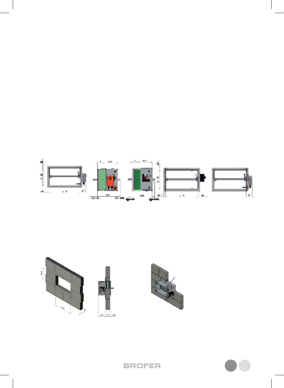
WALL INSTALLATION
1 Before proceeding with the installation, verify the integrity of the damper, the correct positioning of the blade in
the closed position and operation of the command
2 Provide an opening in the wall (Figure 1) having larger dimensions than the nominal size of the damper (see
table 1 according to the type of installation).
3 Positioning the damper at the center of the opening and making sure that the blade in the closed position is
parallel to the wall. Maintain the axis of rotation of the blade horizontally or vertically as from tests carried out.
Observe the projections shown in Figure 2 Table 1
4 Fix the damper to the wall using the brackets, then fill with cement mortar class M10 (Fig. 3.1)
fill with
cement mortar
class M 10
PRECAUTIONS FOR HANDLING AND INSTALLATION
CAUTION!
• All operations of handling and installation shall be made with the blade of the fire damper in the closed position
(our standard delivery).
• All operations of connection power line must be performed by qualified service personnel.
• Keep clean the connecting end from residues of cement to securely connect the rest of the duct
• Avoid any deformation of the duct and / or obstacle inside the duct which may prevent the successful rotation of
the blade
• Check that there are no external obstacles (cables, pipes, etc. ..) to prevent the correct operation of the controls
outside of the duct
• Keep the most accessible as possible to the control side in order to ensure the necessary space usage and mainte-
nance of the damper.
MAINTENANCE
Is advisable to periodically run a check the correct operation of the actuating and signal the damper. In particular,
check the correct and complete opening and closing of the blade: for the operation of the controls follow the instruc-
tions listed “CONTROL OPERATION.” Also check that the warning devices at the beginning and ending are in good
condition and working properly.
DIMENSIONAL
WALL INSTALLATION
1 Before proceeding with the installation, verify the integrity of the damper, the correct positioning of the blade in
the closed position and operation of the command
2 Provide an opening in the wall (Figure 1) having larger dimensions than the nominal size of the damper (see
table 1 according to the type of installation).
3 Positioning the damper at the center of the opening and making sure that the blade in the closed position is
parallel to the wall. Maintain the axis of rotation of the blade horizontally or vertically as from tests carried out.
Observe the projections shown in Figure 2 Table 1
4 Fix the damper to the wall using the brackets, then fill with cement mortar class M10 (Fig. 3.1)
fill with
cement mortar
class M 10
fig.1
fig.2
fill with mortar
class M 10
 Loading...