Do you have a question about the Brook ZERO-PI and is the answer not in the manual?
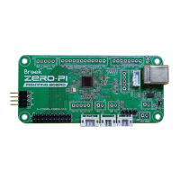
Four USB connection selections for NS/PS3/PC(X-Input)/Retro Gaming Emulator.
Shows how to select J2 or J3 for Player LED indication.
Diagram illustrating the layout and function of various buttons on the board.
Details the pinout for the J4 and J13+J14 headers for connecting cables.
Provides the pinout diagram for the J16 screw terminal block.
Explains how to set and clear turbo functions using specific buttons and LEDs.
Instructions on switching between Left Stick (LS), Right Stick (RS), and D-Pad (DP) modes.
Details the connector for PS/PS2 compatibility and manual mode switching.
| Brand | Brook |
|---|---|
| Model | ZERO-PI |
| Category | Computer Hardware |
| Language | English |