43
V. 4.1-04-08-21
brookvent.co.uk
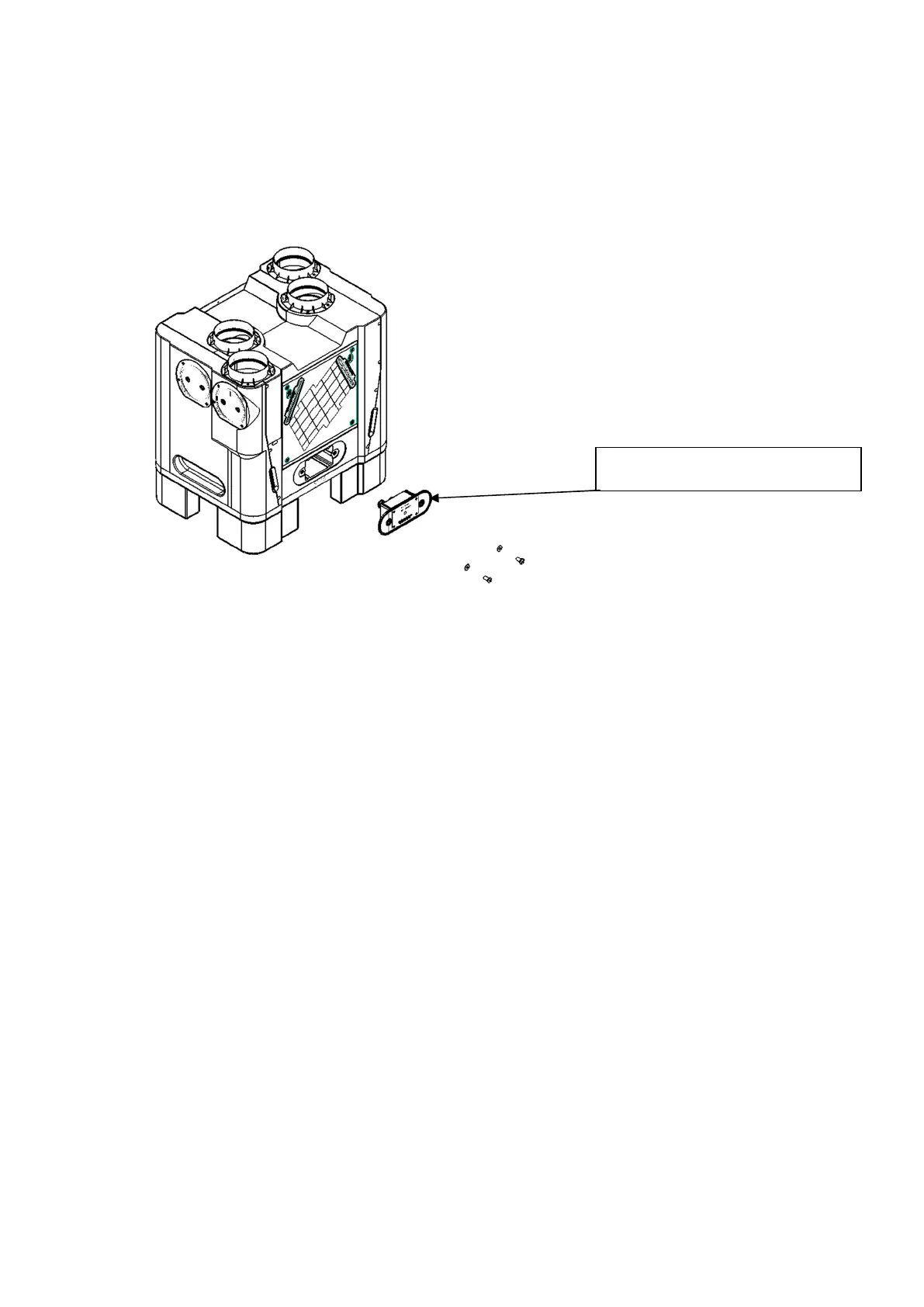
7.5 PCB Module Replacement
In the unlikely event of an electronic PCB failure, the Aircycle 4.1’s PCB module can be
easily disconnected and replaced.
Step 1. Isolate the unit from the mains and ensure all supply circuits are disconnected.
Step 2. Disconnect the mains from the fused spur.
Step 3. Disconnect the Ethernet cable from the socket or junction box.
Step 4. Unscrew the two large screws in the front of the control panel and pull out the
PCB assembly.
Step 5. Unplug all the leads, the connectors are all marked to match up with their
corresponding internal connections.
Step 6. Feed the mains cable from the replacement assembly through the unit and out
the through the hole in the back plate.
Step 7. Connect all the cables back up ensuring to connect each cable to the correctly
marked connector.
Step 8. Replace the assembly in the pocket and secure in place with the screws.
Step 9. Connect the mains to the fused spur.
Step 10. Crimp the RJ45 to the Cat 5e cable if connected to a socket; Otherwise connect
to the junction box
PCB Module
 Loading...