Ill
Explanation
of
connectors
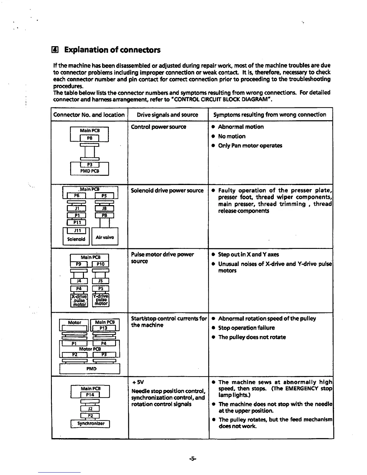
If
the
machine
has
been disassembled
or
adjusted during repair work, most
of
the
machine
troubles
are
due
to
connector problems including improper connection
or
weak contact.
It
is,
therefore,
necessary
to
check
each connector number and pin contact
for
correct connection prior
to
proceeding
to
the troubleshooting
procedures.
The
table
below
lists
the
connector numbers and symptoms resulting
from
wrong
connections. For detailed
connector and harness arrangement, refer
to
•coNTROL
CIRCUIT
BLOCK
DIAGRAM•.
Connector No. and location
Main
PCB
I P8 I
I P3 I
PMDPCB
I
.MainPCB I
I
P6
I I
PS
I
m [5[5
ElBg
I J11 I
Solenoid
Air
valve
~In~
~~
PS
Y
nlsve.
pu
a
motor
I
Motor
ll
Main
PCB
I
-[ L
·I
P13
LJ
;.
I:
:I
I:
1:
:~M+r:
:1
I I I
1
I
I
PMD
I
I I
Main
PCB
I P14 I
~
I
P2
I
r.
Synchronizer
l
Drive signals and source
Control
power
source
Solenoid drive power
source
Pulse
motor
drive
power
source
Symptoms resulting from wrong connection
• Abnormal motion
•
Nomotion
• Only Pan
motor
operates
•
Faulty
operation
of
the
presser
plate,
presser
foot,
thread
wiper
components,
main
presser,
thread
trimming ,
thread
release components
• Step out
in
X and Y
axes
• Unusual noises
of
X-drive
andY-drive
pulse
motors
Start/stop
control currents
for
• Abnormal rotation speed
of
the
pulley
the
machine
+SV
Needle stop position control,
synchronization control, and
rotation control signals
..
s-
• Stop operation failure
• The pulley
does
not
rotate
• The
machine
sews
at
abnormally
high
speed,
then
stops. (The EMERGENCY
stop
lamp
lights.)
• The machine does
not
stop with
the
needle
at
the
upper position.
• The pulley rotates,
but
the
feed mechanism
does
not
work
.
 Loading...