Do you have a question about the Brother DCP-HL-2280DW and is the answer not in the manual?
Comprehensive list of all technical specifications for the models.
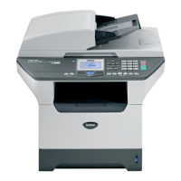
Provides basic general specifications such as print method, resolution, and CPU.
Details wired and wireless network capabilities and security settings.
Information on machine life, monthly volume, and periodical maintenance parts.
Details approximate life expectancy of toner cartridges and drum units.
Specifies paper handling capabilities and media specifications for various trays.
Details modem speed, transmission speed, and fax capabilities.
Specifies copy speed (ADF) and first copy out time for different models.
Provides optical and interpolated resolution, and scanning speed details.
Explains the purpose of the chapter and provides general troubleshooting precautions.
Lists various error codes, their problems, and corresponding page references for solutions.
Detailed table of error codes, problems, and refer-to page numbers for troubleshooting.
Lists error messages displayed on the LCD and their descriptions.
Provides step-by-step remedies for specific error codes like 0B, 0E, 0F.
Addresses issues like pickup failure, no feeding, double feeding, and paper jams.
Provides examples of image defects and their troubleshooting steps.
Details potential issues with main PCB, power supply PCBs, and NCU ASSY.
Outlines essential safety warnings and precautions for maintenance work.
Provides an illustrated list of all screws used in the machine.
Specifies the correct tightening torque for each screw type and location.
Provides a visual flowchart for the disassembly and re-assembly sequence.
Detailed, step-by-step instructions for disassembling and reassembling the machine.
Detailed steps for removing the Automatic Document Feeder (ADF) unit.
Detailed steps for disconnecting harnesses and removing the fuser unit.
Detailed procedure for removing the Main PCB ASSY.
Procedure to remove the motor drive sub assembly and main motor.
Steps for rewriting firmware, initializing EEPROM, and setting country after main PCB replacement.
Detailed instructions for checking firmware version and rewriting it using a computer.
Steps required after replacing the laser unit, including inputting adjusted values.
Steps to reset the irregular power supply detection counter after replacing LVPS PCB.
Checks and operations after replacing the panel unit or LCD unit.
Procedure to check LCD operation using maintenance mode code 12.
Explains how to enter and use the maintenance mode for diagnostics and settings.
A categorized list of all available maintenance mode functions with refer-to pages.
Detailed explanations and operating procedures for various maintenance functions.
Initializes EEPROM settings and worker switches to factory defaults.
Checks the operational status of various sensors within the machine.
Resets counters after replacing fuser unit or paper feeding kit.
Covers functions beyond standard maintenance mode operations.
Resets counters for periodical replacement parts or consumables.
Provides detailed circuit diagrams for various PCBs like High Voltage and Low Voltage power supplies.
Shows the overall wiring diagram for PCB connections within the machine.
States that there are no parts that require periodic replacement.
Explains how to read and locate the machine's serial number label.
Details the procedure for deleting user settings and network information.
Step-by-step guide for installing the maintenance driver for multiple machine identification.
Instructions on how to create protective material for the drum unit for packing.
| Type | printer, copier, scanner |
|---|---|
| Color | black |
| Tray Capacity | 250 |
| Paper Size | letter, legal, executive, folio, a4, a5, a5 (long edge), a6, b5 (iso/jis), b6 (iso) |
| Paper Handling | up to 250 sheets |
| Mono Print Speed | 27 pages per minute |
| Print Resolution Mono | up to 2400 x 600 |
| Maximum Number of Pages Per Month | up to 10, 000 |
| Scanner Type | flatbed |
| Scan Resolution | up to 19200 x 19200 |
| Max Copies | 99 |
| Number Of Cartridges | 2 |
| Internal Memory | yes |
| Network | wired/wireless |
| Connectivity | usb, ethernet |
| OS Compatibility | windows 2000, xp, xp x64, vista, server 2003/2008 or 7, mac os x 10.4.11, 10.5.x or 10.6.x |
| Mobile Devices Connection | yes |
| Height | 15.9 inches |
|---|---|
| Width | 15.7 inches |
| Net Weight | 22.7 pounds |