Do you have a question about the Brother FS-40 and is the answer not in the manual?
Diagram showing the main functional mechanisms of the sewing machine.
Explanation of the power transmission and movement systems within the machine.
Diagrams illustrating the location of electronic parts on the machine.
A schematic showing the interconnections of the machine's electronic control system.
Details on how various electronic components function during operation.
Location diagram and removal steps for major machine components.
Disassembly and assembly procedures for electrical components and motors.
Steps for disassembling and assembling needle and presser mechanisms.
Procedures for disassembling and assembling the feed mechanism.
Steps for disassembling and assembling the bobbin winder mechanism.
Attachment procedures for main external machine parts.
Assembly procedures for electrical components and motors.
Assembly procedures for needle and presser mechanisms.
Assembly procedures for the bobbin winder mechanism.
Steps for assembling the feed and rotary modules.
Assembly procedures for the needle-presser module.
Procedures for entering and operating test modes for adjustments.
How to adjust the tension of the timing belt for optimal performance.
Procedure for adjusting the motor belt tension.
Method for adjusting the upper thread tension using a tension gauge.
Adjustment for needle drop position in the left base line.
How to set the correct position of the rotary hook unit.
Adjusting the clearance between the needle and the outer rotary hook.
Adjusting the needle bar's raised position relative to the hook.
Setting the correct vertical height of the needle bar.
Adjusting the front/back clearance between needle and rotary hook.
Adjustment procedure for the needle threader mechanism.
Adjusting the presser bar's height and alignment.
Adjusting the feed dog's forward and backward movement.
Adjustment procedure for the bobbin winder mechanism.
Setting the correct position of the BH lever switch.
Adjusting the front/back position of the needle and presser foot.
Adjusting the feed dog's position.
Setting the correct height of the feed dog.
Adjusting the position of the inner rotary hook bracket.
Adjusting the tension of the lower thread in the rotary hook.
A table listing error messages and their probable causes.
Troubleshooting flowcharts for specific error messages.
Troubleshooting steps when the machine does not power on.
Diagnosing issues with the pulse motor's initial positioning.
Troubleshooting steps when patterns cannot be selected.
Diagnosing why the main motor fails to rotate.
Troubleshooting abnormal main motor rotation or speed issues.
Steps to troubleshoot incorrect pattern sewing.
Diagnosing issues with sewing buttonholes correctly.
Troubleshooting when operation buttons are unresponsive.
Diagnosing problems with foot controller operation.
Troubleshooting issues with bobbin winding.
Diagnosing why the LED lamp is not functioning.
Troubleshooting abnormal LCD display issues.
Diagnosing why the buzzer is not making sound.
Detailed wiring instructions for the needle bar and presser modules.
Wiring instructions for the power supply unit.
Wiring instructions for components located in the front cover.
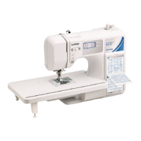
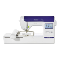
| Stitch Number | 40 |
|---|---|
| Buttonhole Styles | 5 |
| Display | LCD |
| Lighting | LED |
| Type | Electronic |
| Needle Threading | Automatic |
| Adjustable Stitch Length | Yes |
| Adjustable Stitch Width | Yes |
| Maximum Stitch Width | 5 mm |
| Maximum Stitch Length | 4 mm |
| Reverse Sewing | Yes |
| Free Arm | Yes |
| Start/Stop Button | Yes |
| Speed Control | Yes |
| Bobbin | Top-loading |
| Sewing Speed | 750 stitches per minute |