COOLING SYSTEM
HOSE ROUTING AND WATER FLOW DIAGRAMS
227
9
HOSE ROUTING AND WATER FLOW DIAGRAMS
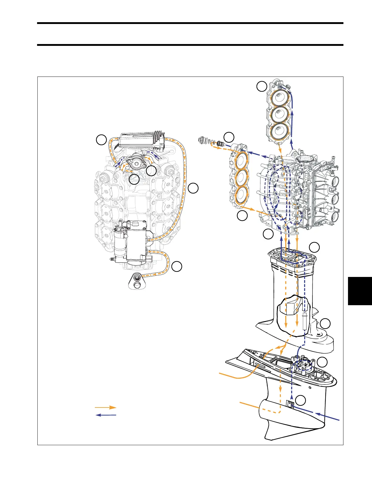
V6 MODELS
Hose Routing & Water Flow Diagram
150-200 HP/60°V6
Outgoing water (warm/hot)
Incoming Water (cool)
1. Water intake screens
2. Water pump
3. Water tube
4. Adaptor/exhaust housing
5. Cylinder block
6. Thermostat
7. Pressure valve
8. Cylinder head, water outlet
9. Cylinder block vent
10. Water supply to EMM
11. Water supply, EMM to vapor separator
12. Vapor separator to overboard indicator
12
11
10
9
8
7
6
6
5
4
3
2
1
Outgoing water (warm/hot)
Incoming water (cool)
1.
2.
3.
4.
5.
6.
7.
8.
9.
10.
11.
12.
Water intake screens
Water pump
Water tube
Adapter housing
Cylinder block
Thermostat
Pressure valve
Cylinder head, water outlet
Cylinder block vent
Water supply to EMM
Water supply, EMM to vapor separator
Vapor separator to overboard indicator