Effectivity: 916 i A / C24
Edition 0 / Rev. 1
BRP-Rotax Page 7-13
December 01 2023
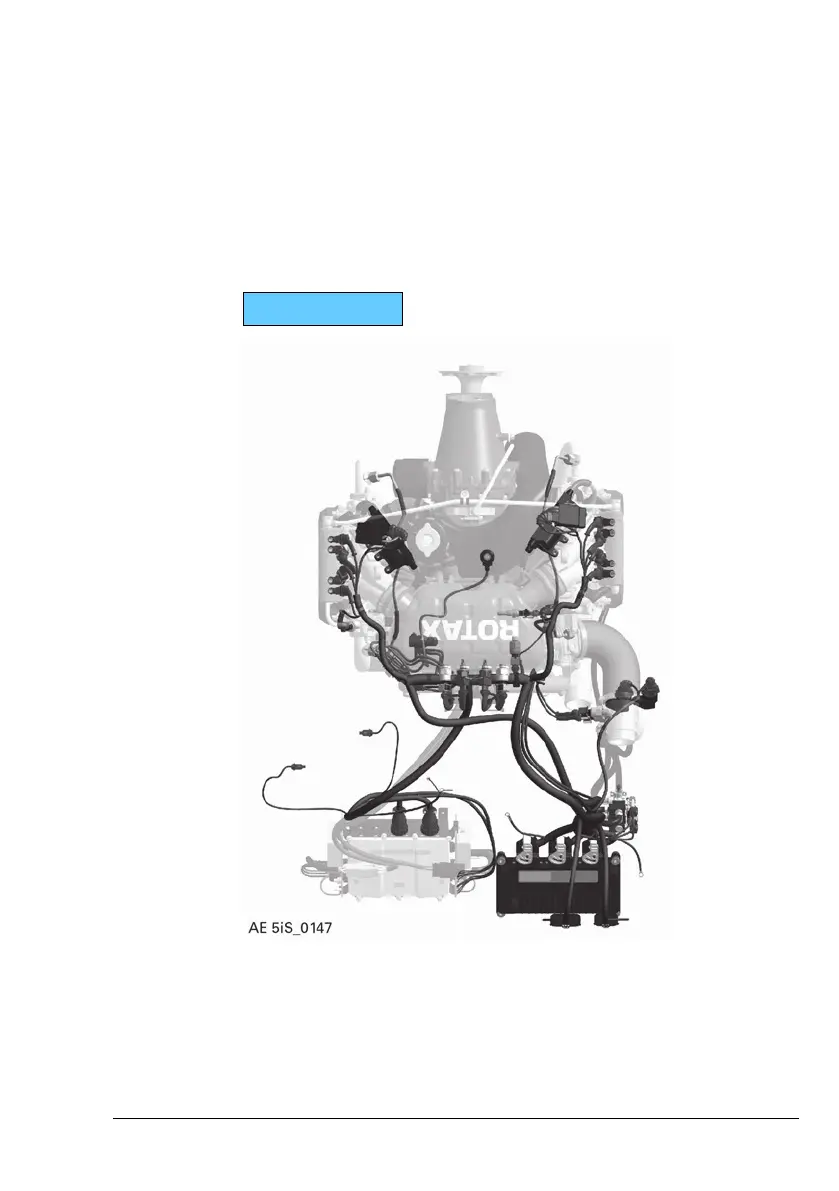
Lane to take over control of the engine. A huge quantity of sen-
sors (e. g. sensors for measuring the pressure in the airbox)
and actuators (e. g. ignition coils) of the engine is designed with
redundancy. In this case, each of the sensors or actuators are
connected to a Lane, so that the two Lanes have the same
measurement values and send the same output signals. Non-
redundant sensors (e. g. oil pressure sensors) are connected to
one Lane only and serve for the expanded monitoring of the en-
gine functionality. Due to an ECU internal communication, these
sensor values will be exchanged between the two Lanes (as-
suming that both Lanes are active and free of errors).
916 i TYPE A
Figure 11: Management System

 Loading...


