Do you have a question about the BRP EVINRUDE E-TEC E40DRLAA Series and is the answer not in the manual?
Provides essential safety information and symbol definitions for operating and servicing the outboard.
Lists and defines abbreviations used throughout the service manual for clarity and reference.
Details federal law requirements and responsibilities for emissions control on marine engines.
Explains the system for designating outboard models, including prefixes, horsepower, and features.
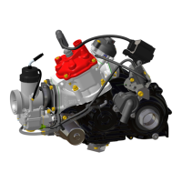
Provides detailed technical specifications for 40-60 HP Evinrude E-TEC AA models.
Provides detailed technical specifications for 40-60 HP Evinrude E-TEC AB models.
Lists standard torque specifications for various fastener sizes when a specific torque is not listed elsewhere.
Provides a schedule of routine inspections and maintenance tasks to prolong outboard life.
Covers common practices for rigging and connecting control cables, ensuring proper function.
Details various adjustments for steering friction, throttle friction, and tilt limits for optimal performance.
Describes the cooling system components, operation, and checks for proper function and temperature.
Covers lubrication procedures for the steering system, tiller handle, swivel bracket, and gearcase.
Focuses on maintenance and inspection of the fuel filter, oil filters, and related system components.
Details procedures for protecting metal components and exterior finishes from corrosion.
Provides instructions for proper storage procedures, including fuel system treatment and engine preparation.
Outlines essential checks and recommendations for preparing the outboard after storage.
Provides critical service procedures for outboards that have been submerged in water.
Covers the service procedures for the upper engine cover, including latch hook installation.
Details the removal and installation procedures for the lower engine cover and associated components.
Provides instructions for installing the latch handle, ensuring proper alignment and security.
Explains the procedure for installing the trim switch, including electrical connections.
Details the various functions controlled by the EMM, including ignition, fuel, and diagnostics.
Provides important information regarding EMM connections and wiring integrity for proper operation.
Describes the function and troubleshooting of internal sensors monitored by the EMM.
Details the function and troubleshooting of external sensors connected to the EMM.
Explains how to use Evinrude Diagnostics software for troubleshooting and system adjustments.
Covers the procedure for establishing communication between the EMM and a computer.
Describes how to view static information, including manufacturing details and model identification.
Explains how to view dynamic information, such as real-time voltage and temperature data.
Details how service codes are saved when abnormal conditions occur and how to review them.
Guides for performing diagnostic tests on system components while the outboard is not running.
Explains how to perform dynamic tests to isolate faulty cylinders or identify performance issues.
Provides detailed diagrams and pinouts for engine harness and EMM connectors.
Details the importance of ground connections and procedures for testing them.
Covers tests for various sensors, including CPS, TPS, and temperature sensors, with resistance values.
Explains how to perform resistance and voltage output tests on the stator for proper diagnosis.
Provides procedures for testing the 12 V and 55 V charging circuits to ensure proper battery operation.
Details tests for the starter solenoid and voltage drop to diagnose starting system issues.
Covers tests for key switch and neutral start circuit operation to ensure control system integrity.
Explains how to test the emergency stop system to ensure it functions correctly.
Provides procedures for testing the SystemCheck warning lights and horn for proper function.
Covers the removal and installation procedures for the flywheel and stator components.
Details the removal and installation procedures for the ignition coils.
Explains how to adjust and verify ignition timing, ensuring synchronization between EMM and crankshaft.
Guides on calibrating the Throttle Position Sensor to ensure accurate throttle plate opening.
Covers the removal and installation procedures for the electric starter motor.
Provides detailed procedures for servicing Deutsch, AMP, and Packard connectors.
Details regulations and guidelines for boat fuel systems, including flow and component requirements.
Describes the various components of the fuel system, including pumps, filters, and injectors.
Explains the fuel lift pump operation, pulse hose location, and serviceability.
Details the function of the fuel filter and its role in protecting system components.
Describes the vapor separator's function as a fuel reservoir and its components.
Explains the function of fuel injectors as metering devices and the EMM's control over them.
Provides instructions for priming the fuel system, including vent line clamp removal.
Covers various tests for the fuel system, including pressure, injector, and pump tests.
Details the procedure for testing fuel system pressure, including normal, high, and low pressure conditions.
Explains how to perform a pressure test on fuel injectors to verify their operation.
Provides the procedure for measuring the resistance of fuel injector coils and circuits.
Details how to test the lift pump pressure to ensure adequate fuel supply.
Explains how to test for vacuum and restrictions in the fuel supply to the lift pump.
Covers servicing procedures for fuel components, including filter, lift pump, and vapor separator.
Provides instructions for the removal, disassembly, and cleaning of the intake manifold.
Details the recommended lubricants and engine lubricant specifications for various conditions.
Lists and describes the components of the oiling system, including the oil tank and pump.
Explains the operation of the oil injection pump and its electrical circuit.
Describes the low oil warning system and the EMM signals indicating low oil levels.
Details the conditions under which the NO OIL warning activates and the EMM's response.
Covers settings for oil injection rate, including TC-W3 and XD100 options.
Explains how EMM programming controls the oil injection rate based on RPM and oil type.
Provides instructions for break-in oiling procedures for new or rebuilt powerheads.
Details the procedure for priming the oiling system using Evinrude Diagnostics software.
Covers various tests for the oiling system, including voltage, resistance, and flow tests.
Explains how to test the oil injection pump voltage supply and control signal.
Provides the procedure for measuring the resistance of the oil injection pump winding.
Details how to test the oil injection pump's function by observing oil flow.
Covers servicing procedures for oil distribution hoses and the oil tank assembly.
Illustrates the routing of hoses and the flow of cooling water through the outboard.
Describes key cooling system components, including water pump, exhaust housing, and thermostat.
Details the operation and service of the water pump and its external water intakes.
Describes the exhaust housing and its role in cooling the cylinder block.
Explains the function of the thermostat in controlling water flow and operating temperature.
Details the function of the pressure relief valve in controlling water flow at higher speeds.
Describes the two-stage cooling system operation, dependent on water pump and thermostat.
Explains the water flow path for cooling the cylinder block and head via thermostat and relief valve.
Provides methods for checking engine operating temperatures using software or a pyrometer.
Guides for troubleshooting low idle operating temperatures, checking thermostat and relief valve.
Covers the removal, cleaning, and installation of the temperature sensor.
Details the disassembly, inspection, and assembly of the thermostat.
Provides procedures for the disassembly, inspection, and assembly of the pressure relief valve.
Provides an exploded view of powerhead components with torque specifications and lubricant references.
Details the procedure for performing a compression test on engine cylinders.
Covers the step-by-step process for removing the powerhead from the outboard.
Guides the user through the process of disassembling the powerhead and removing various systems.
Outlines the removal of major systems like starter, oil tank, fuel pumps, and EMM.
Details the procedure for disassembling the crankcase, including removing covers and nuts.
Provides instructions for removing the cylinder head, including thermostat and seal replacement.
Covers the identification, removal, and handling of connecting rods and pistons.
Details the safe removal of the crankshaft, including seals and bearings.
Provides instructions for cleaning cylinder block and head, removing carbon deposits and contaminants.
Guides on visually inspecting powerhead components for wear, damage, or discoloration.
Covers the complete assembly process for the powerhead, including crankshaft and bearing installation.
Details the installation of crankshaft bearings, sleeves, and seals.
Explains the correct installation of pistons and connecting rods, including alignment and lubrication.
Outlines final procedures after powerhead installation, including timing, calibration, and leak checks.
Provides visual references of powerhead hose routings and dressed configurations.
Provides exploded views of midsection components with torque specifications and lubricant references.
Details the removal and installation of the exhaust housing for 40-60 HP models.
Covers the process of removing the exhaust housing, including preparatory steps.
Details the removal, installation, and servicing of the exhaust water valve for 60 HP models.
Explains how to inspect, clean, or replace the exhaust relief muffler filter element.
Provides step-by-step instructions for installing the exhaust housing.
Details the removal and installation of the exhaust housing for 75-90 HP models.
Covers the inspection and replacement of lower mounts for the exhaust housing.
Guides through the disassembly of the exhaust housing, including adapter and water tube removal.
Details cleaning procedures and inspection for distortion of the exhaust housing.
Provides instructions for assembling the exhaust housing, including gasket and grommet installation.
Details the disassembly and assembly of the stern bracket for 40-60 HP power tilt models.
Covers the removal of bumpers, screws, and seals for stern bracket disassembly.
Provides instructions for assembling the stern bracket, including lubrication and torque values.
Details the disassembly and assembly of the stern bracket for 75-90 HP power tilt models.
Covers removal of locknuts, brackets, seals, and bushings for stern bracket disassembly.
Provides instructions for assembling the stern bracket, including rollers, springs, and lock components.
Details the disassembly and assembly of the stern bracket for 40 HP manual tilt models.
Covers removal of bumpers, screws, and linkage components for stern bracket disassembly.
Provides instructions for assembling the stern bracket, including reverse lock mechanisms.
Covers the removal, disassembly, inspection, and assembly of the standard tiller handle.
Details the steps for removing the throttle cable, anchor screw, and retainer.
Guides through the disassembly of the tiller handle, including friction control and helix components.
Provides instructions for installing the tiller handle, including cable and electrical connections.
Explains how to adjust the throttle cable for proper operation and idle stop alignment.
Covers the removal, disassembly, inspection, and installation of the long tiller handle.
Details the final attachment of control cables to shift and throttle levers.
Guides on adjusting the shift cable for proper engagement and alignment.
Provides exploded views of gearcase components with torque specifications and lubricant references.
Covers propeller inspection, selection, and hardware installation for optimal performance.
Details procedures for testing the gearcase for leaks using pressure and vacuum testers.
Provides comprehensive service procedures for the gearcase of 40-60 HP models.
Covers the step-by-step process for removing and installing the gearcase assembly.
Details the disassembly, inspection, and assembly of the water pump.
Explains how to check and adjust the shift rod height for correct gear engagement.
Guides through the disassembly of the gearcase, including pre-disassembly inspection.
Details the removal of the propeller shaft bearing housing and its components.
Covers the removal of the pinion gear and driveshaft assembly.
Guides through the removal of the shift housing, gear, and propeller shaft assembly.
Details service procedures for shifter components, bearings, and seals.
Explains how to shim the driveshaft assembly to achieve correct backlash and clearance.
Provides comprehensive instructions for assembling the gearcase, including shafts and housings.
Guides the installation of the shift housing, gear, and propeller shaft assembly.
Details the installation of the shift rod housing, including O-ring and grommet placement.
Covers the installation of the pinion gear and driveshaft assembly, including shimming.
Provides comprehensive service procedures for the gearcase of 75-90 HP models.
Covers the step-by-step process for removing and installing the gearcase assembly.
Details the disassembly, inspection, and assembly of the water pump.
Explains how to check and adjust the shift rod height for correct gear engagement.
Guides through the disassembly of the gearcase, including pre-disassembly inspection.
Details the removal of the propeller shaft bearing housing and its components.
Covers the removal of the pinion gear and driveshaft assembly.
Explains how to separate and assemble the driveshaft components.
Guides on inspecting the gearcase housing for distortion and bearing alignment.
Details service procedures for shifter components, bearings, and seals.
Covers the removal of the pinion bearing.
Provides instructions for installing the pinion bearing using specialized tools.
Details service procedures for shifter components, bearings, and seals.
Covers servicing procedures for driveshaft bearing housing seals.
Explains how to shim the driveshaft assembly to achieve correct clearance.
Provides exploded views of trim and tilt components with torque specifications and lubricant references.
Describes the power trim/tilt hydraulic system components and optimal boat trimming.
Explains how to manually raise or lower the outboard using the manual release valve.
Covers routine checks for fluid leaks, battery condition, and reservoir fluid levels.
Provides guidelines for diagnosing common trim/tilt unit problems and their possible causes.
Details tests for relays and trim/tilt motor current draw to evaluate electrical system performance.
Explains how to measure current draw and operating speed of the trim/tilt motor.
Provides steps to test the trim gauge operation and its connection to the sender.
Covers testing the trim sender for proper resistance and voltage readings.
Details the removal and installation procedures for the trim and tilt unit.
Covers the removal of the trim/tilt unit, including connectors, pins, and snap rings.
Provides instructions for installing the trim/tilt unit, including lubrication and torque specifications.
Covers servicing procedures for the trim and tilt unit, including manual release valve and piston seal.
Details the procedure for removing and installing the manual release valve, including pressure relief.
Covers the service of the piston and end cap assemblies, including seal and fluid replacement.
Provides removal and installation procedures for the trim motor, including fluid filling.
Provides an exploded view of recoil starter components with torque specifications and lubricant references.
Details the procedure for removing the recoil starter assembly, including clamps and screws.
Guides through the disassembly of the recoil starter, including rope, spring, and pawl components.
Provides instructions for cleaning and inspecting metal components and the starter rope.
Covers the assembly of the recoil starter, including spring, pulley, and pawl installation.
Details the installation of the recoil starter assembly, including ratchet and housing.
Emphasizes the importance of safe practices for users and technicians, including proper parts substitution.
Highlights the importance of correct shift linkage alignment and operation to prevent loss of control.
Focuses on safe operation of the speed control system, ensuring proper neutral gear engagement.
Details the importance of a secure and properly functioning steering system to prevent accidents.
Provides checks for potential issues in transom-mounted steering systems to ensure safe operation.
Covers safety precautions related to fuel handling, electrical systems, and preventing fire or explosion.
Provides critical safety guidelines for handling gasoline, including storage and spill prevention.
Highlights safety precautions for handling hazardous products found in a workshop environment.
A self-assessment test to ensure understanding of the safety precautions in the manual.
| Model | E40DRLAA |
|---|---|
| Series | E-TEC |
| Horsepower | 40 hp |
| Engine Type | 2-Stroke |
| Cylinders | 2 |
| Starting | Electric |
| Full Throttle RPM Range | 5000-6000 RPM |
| Steering | Remote |
| Oil Injection | Yes |
| Gear Ratio | 2.00:1 |
| Fuel System | Direct Fuel Injection |
| Exhaust | Through Prop |
| Shaft Length | Long (20") |