PAGE 4 BRUNSWICK INSTALLATION MANUAL
METRO
BASEFRAME AND LEG ASSEMBLY
(CONTINUED)
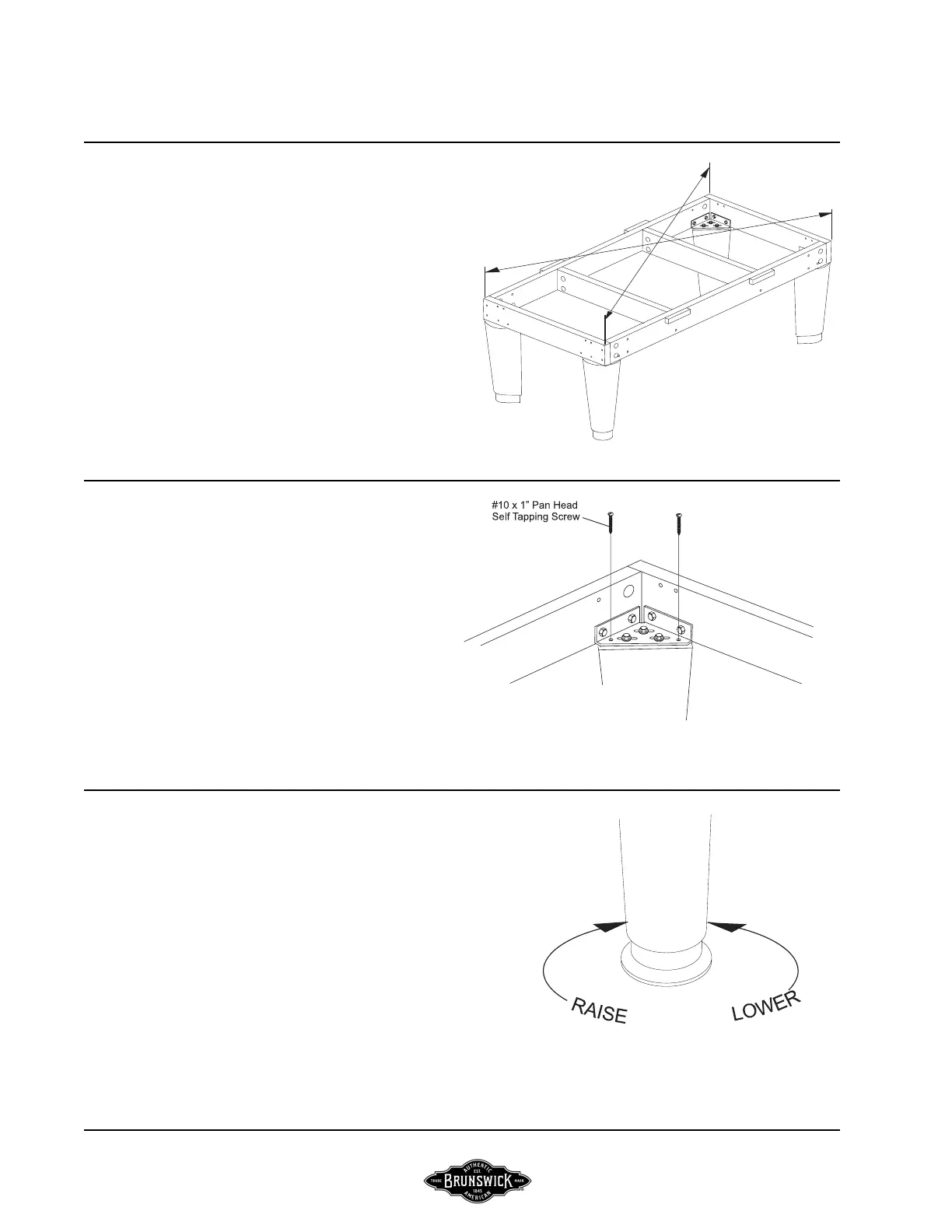
FIGURE FOUR
Step #8: Measure the baseframe assembly diagonally
and adjust as required to obtain the same measurement
to assure the baseframe is square. With all joints flush
and legs aligned properly, tighten all hardware securely.
FIGURE FOUR
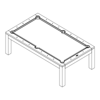
FIGURE FIVE
Step #9: Screw #10 x 1” pan head tapping screws
through the top of each leg bracket into the leg.
FIGURE FIVE
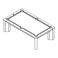
FIGURE SIX
Step #10: Position the baseframe and leg assembly in its
final location. Level the baseframe with your preferred
level by rotating the leg levelers. The levelers should be
rotated out atleast 1/4” to allow for further leveling when
the slate is attached.
NOTE:
Try to leave atleast 5’ between the outer edge
of the baseframe to any wall.
FIGURE SIX