18
INLET
EXHAUST
IN
ON
OFF
V
E
N
T
AIR
FLOW
Street Elbow
1
/
2
CPVC
(Loose parts bag)
Casing Grommet
Black Rubber
5
/
8
ID
(Loose parts bag)
Drain Tee
Drain Connector Black PVC
3
/
4
PVC X
1
/
2
CPVC
(Loose parts bag)
Drain Line Vent Tee
3
/
4
PVC or
1
/
2
CPVC (Field supplied)
Drain Tube
Black Rubber
1
/
2
ID & Clamps
Drain Tube
Corrugated
5
/
8
ID
& Clamps
Relief Tube
Black Rubber
3
/
16
ID
Coupling & Clamps
(Optional)
2 5 -- 2 4 -- 8 0
Single Pressure
Switch
Dual Pressure Switch Detail
Drain Tube Black Rubber
5
/
8
ID & Clamps,
Cut length to fit (Loose parts bag)
On Some Models
ONLY
Plastic Caps (2)
Yellow or black
Vent Drain
&Clamps
Representative drawing only, some models may vary in appearance.
A07706
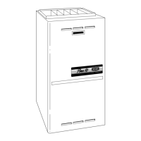
Fig. 10 -- Upflow Installations Top Vent
Upflow Installations Top Vent (See Fig.
10)
S Remove knockout from the side of the furnace casing where
drain tube will exit.
S Install casing grommet (black rubber
5
/
8
″ (16 mm) ID
grommet -- in loose parts bag)
S Install the
1
/
2
″(13 mm) CPVC street elbow on discharge of trap
S Install the black PVC tube connector (
3
/
4
″ (18 mm) PVC x
1
/
2
″
(13 mm) CPVC from loose parts bag) as shown in the
illustration above.
S Cut the black drain tube (
5
/
8
″(16 mm) ID -- in loose parts bag)
to length to fit between trap and tube connector through
grommet.
S Clamp both ends of the drain tube using clamps provided.
S Glue the CPVC street elbow to the trap using appropriate
cleaner and solvent cement.
S The field supplied
3
/
4
″ PVC or
1
/
2
″(13 mm) CPVC drain line
vent tee must vent outside the furnace cabinet (see exploded
view above).
NOTE: It is recommended that all PVC piping and fitting
connections be fit up and inspected before final cementing. Trap
must be primed before operation. Verify all condensate drain
connections are securely clamped. A coupling and clamps (in
loose part bag) may be installed as shown for future servicing of
the vent system.
NOTE: “PVC” is used as a generic term. Pipe and fitting
materials used must be acceptable to the local code officials
having jurisdiction.
359AAV