40
A07729
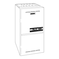
Fig. 42 -- Side Mounted Filter Rack
Filter Installation using Optional Filter Rack
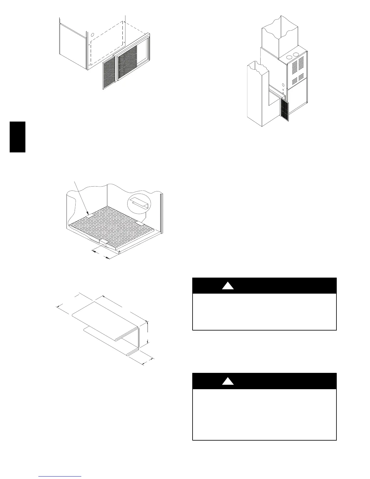
When installing or removing a bottom mounted filter, slide the
two side filter clips to the back of the furnace BEFORE installing
or removing. This will allow the filter to clear the front raised
edge of the furnace. Insert filter into side clips first and push filter
back until it is fully engaged into back clip. When filter is in
place, slide clips back into place midway on filter as shown in
Fig. 43 and Fig. 44.
Slide filter clips towards back before removing
25--24--18--1
Center Clip
s i d e -- t o -- s i d e
9″ (152.4mm)
A07691
Fig. 43 -- Bottom Mounted Filter Rack
3
1
1
/
4
1
1
/
2
11
/
16
26 Ga. Galvanized Steel
FAST part number 1008482
(38.1)
(31.8)
(76.2)
(27)
in.
in.
in.
in.
A07730
Fig. 44 -- Filter Clip Construction
Refer to Fig. 45 and for guidelines to install filters. Furnaces
which require larger filter media and have limited clearances on
one side of furnace, require a standoff filter rack, see Fig. 45,
available from your distributor.
Using Optional
Standoff Filter
Rack
A07731
Fig. 45 -- Standoff Filter Rack
Addition Of Air Conditioning
When a refrigeration coil is used in conjunction with this unit, it
must be installed parallel with or on the discharge side of the unit
to avoid condensation on the heat exchanger. All furnaces are
designed with a break--away duct flange on the supply air side of
the furnace. This allows for installation in the horizontal right or
downflow applications. The coil installation instructions must be
consulted for proper coil location and installation procedures.
With a parallel flow arrangement, dampers must be installed to
prevent chilled air from entering the furnace. If manually
operated dampers are used, they must be equipped with a means
to prevent operation of either unit unless the damper is in full heat
or full cool position.
A3″ (76 mm) clearance is required on the right side of the
furnace in order to run the condensate drain line. Copper or
plastic tubing may be used for the condensate drain line.
CHECKS AND ADJUSTMENTS
NOTE: Verify the input rate of the furnace.
FIRE OR EXPLOSION HAZARD
Failure to follow this warning could result in personal injury,
death and /or property damage.
Turn OFF gas at shut off before connecting manometer.
!
WARNING
Start-up
NOTE: Refer to the start--up procedures in the “User’s
Information Manual”ortothe“Operating Instructions Label”on
the furnace.
ELECTRICAL OPERATION HAZARD
Failure to follow this warning could result in personal injury,
death, and/or property damage.
If any sparks, odors or unusual noises occur, immediately shut
OFF power to the furnace. Check for wiring errors or
obstruction to blower.
!
WARNING
359AAV