EasyManua.ls Logo

Bryant 559D - User Manual

Bryant 559D
8 pages
Print Icon
To Next Page IconTo Next Page
Loading...
IMPORTANT READ BEFORE INSTALLING
1. Read and become familiar with installation instruc-
tions before installing accessory economizer.
2. Be sure installation conforms to all local and national
codes.
SAFETY CONSIDERATIONS
Recognize safety information. This is the safety-alert symbol
( ). When you see this symbol on the unit and in instruc-
tions or manuals, be alert to the potential for personal
injury.
Understand the signal words DANGER, WARNING and
CAUTION. These words are used with the safety-alert sym-
bol. Danger identifies the most serious hazards which will
result in severe personal injury or death. Warnings, on the
other hand, could result in personal injury. Caution is used
to identify unsafe practices which would result in minor per-
sonal injury or product and property damage.
WARNING:
Before performing service or mainte-
nance operations on unit, turn off main power switch
to unit. Electrical shock could cause personal injury.
INSTALLATION
WARNING:
Turn off unit power! Electrical shock and
personal injury could result.
Install economizer damper assembly as follows:
1. If base unit is installed and in operation, turn off all
power to unit.
2. Remove filter access panel then remove 25% air/
economizer hood. See Fig. 2 and 11.
3. Remove and discard 25% outdoor-air damper section.
Save screws. See Fig. 3.
4. Remove and discard shorting plug located in left front
of return-air compartment and behind unit control box.
See Fig. 3.
5. Remove economizer damper assembly from shipping car-
ton. Remove economizer control box cover. See Fig. 4.
6. Slide economizer into unit opening as shown in Fig. 5.
Package Contents
ITEM # ITEM NAME ITEM # ITEM NAME
1 Frame, Middle 32 Connector, Wire
2 Frame, Bottom 33 Motor, Damper
3 Frame, Top 34 Screw (40)
4 Frame, Side 35 Screw (4)
5 Frame, Side 36 Wire Tie (3)
6 Frame, Middle 37 Bolt, Capscrew (4)
7 Channel, End 38 Washer, Lock (4)
8 Channel, Support 39 Washer, Plate (4)
9 Channel, End 40 Nut (4)
10 Blade, Damper (6) 41 Control
11 Blade, Damper (2) 42 Shaft
12 Thermistor 44 Shield
14 Screw (16) 46 Seal Strip
15 Screw (2) 47 Seal Strip (4)
16 Bar 49 Channel
17 Bar 50 Seal Strip (4)
18 Rod, Linkage 52 Seal (4)
19 Bracket, Sensor 54 Switch, Temp
20 Bearing (12) 55 Plug Asy
21 Shaft (3) 56 Wire Asy
22 Shaft (6) 57 Wire Asy
23 Lever, Damper (5) 58 Wire Asy
24 Screw, Hex Head (5) 59 Wire Asy
25 Nut (5) 60 Wire Asy
26 Pin (4) 61 Wire Asy (2)
27 Cotter Pin (4)
28 Washer (3)
29 Linkage (2)
30 Bushing, Snap (2)
NOTE: If quantity of item is more than one, number of items is listed in parenthesis after the item
name. Example: Screw (16). See Fig. 1 for economizer details.
installation instructions
ACCESSORY INTEGRATED
ECONOMIZER
P/N 389041-201
542F, 559D,
579D, 599D
Cooling Sizes
150, 180 & 216
Cancels: 40579DP426-B IIK 559D-150-1
3/2/92
Question and Answer IconNeed help?

Do you have a question about the Bryant 559D and is the answer not in the manual?

Overview

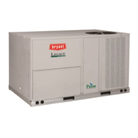
This document outlines the installation, operation, and maintenance of the Bryant/Day & Night/Payne Accessory Integrated Economizer, P/N 389041-201, for 542F, 559D, 579D, and 599D cooling units (sizes 150, 180 & 216).

The economizer is designed to provide "free cooling" by utilizing cooler outdoor air when conditions are suitable, thereby reducing the need for mechanical refrigeration and saving energy. It integrates with the existing HVAC unit to modulate outdoor and return air dampers based on enthalpy control.

Function Description:

The economizer system consists of a damper assembly, an enthalpy control module, a damper motor, and various sensors. Its primary function is to bring in outdoor air for cooling when the outdoor air's enthalpy (a measure of its total heat content, including both dry-bulb temperature and humidity) is lower than the return air's enthalpy or a set point. This allows the unit to cool the space without engaging the compressor, leading to energy savings.

The system operates in conjunction with the unit's thermostat. When a call for cooling is initiated, the enthalpy control module evaluates outdoor air conditions. If the outdoor air is suitable for free cooling, the economizer's outdoor-air damper opens, and the return-air damper modulates to mix outdoor and return air to achieve the desired supply air temperature. If outdoor air conditions are not suitable, the economizer's dampers move to a vent position, and the mechanical cooling system (compressor) takes over.

A freeze protection thermostat (FPT) is included, located on the indoor coil, to prevent ice buildup. If ice is detected, the compressor is turned off, allowing the coil to clear. Once the ice melts, the compressor can be re-energized.

In the event of a power loss, the damper is equipped with a spring return mechanism that automatically closes the dampers to prevent uncontrolled airflow.

Important Technical Specifications:

The economizer is compatible with specific Bryant, Day & Night, and Payne cooling units (542F, 559D, 579D, 599D) in cooling sizes 150, 180, and 216. Key components include:

  • Damper Assembly: Consists of multiple blades (Item 10, 11) controlled by a damper motor (Item 33) and linkage (Item 18, 29).
  • Enthalpy Control Module (Item 41): The brain of the economizer, it evaluates sensor inputs and controls damper position. It includes an enthalpy changeover setpoint dial and a minimum position adjustment screw.
  • Enthalpy Sensor (Item 57): Measures outdoor air enthalpy. The standard configuration uses a solid-state enthalpy sensor (HH57AC078).
  • Mixed-Air Sensor (Item 59): Measures the enthalpy of the mixed outdoor and return air.
  • Temperature Switch (Item 54): A cooling lockout switch that prevents compressor operation below 50°F outdoor-air temperature.
  • Wiring Harnesses (Item 55-61): Connect various components.
  • Power Requirements: Operates on 24 VAC (TR, TR1 terminals).

Usage Features:

  • Energy Savings: By using outdoor air for cooling when conditions permit, the economizer significantly reduces reliance on the compressor, leading to lower energy consumption.
  • Automatic Operation: Once installed and configured, the economizer automatically modulates dampers based on outdoor air conditions and thermostat calls.
  • Adjustable Enthalpy Setpoint: The enthalpy control module allows adjustment of the setpoint (A, B, C, D ranges) to define when outdoor air is considered suitable for free cooling. This can be fine-tuned based on desired temperature and relative humidity.
  • Minimum Position Adjustment: A screw on the enthalpy control module allows setting a minimum outdoor air damper position, ensuring a certain amount of fresh air is always introduced, even when not in free cooling mode.
  • LED Indicator: The enthalpy control module features an LED that lights up to indicate when outdoor air is suitable for free cooling, aiding in troubleshooting and setup.
  • Differential Enthalpy Control (Accessory): An optional kit (HH57AC078) allows for differential enthalpy control, comparing outdoor air enthalpy to return air enthalpy for more precise free cooling decisions.

Maintenance Features:

  • Outdoor-Air Inlet Screens: These screens should be periodically loosened, removed, and cleaned with steam, hot water, and detergent to ensure proper airflow. They are not disposable filters.
  • Economizer Adjustments: Regular checks and adjustments are recommended to ensure optimal performance. This includes verifying full closure of the outdoor-air damper and full opening of the return-air damper.
  • Damper Vent Setting: The minimum vent position should be adjusted periodically to ensure proper fresh air intake.
  • Enthalpy Control Checkout Procedures: Detailed procedures are provided for both solid-state and differential enthalpy controls to verify their functionality. This involves simulating low enthalpy conditions using refrigerant spray on the sensor and observing damper movement and LED indicators.
  • Accessibility: The filter access panel (Fig. 2) must be removed to gain access to the enthalpy control, mixed-air thermostat, and damper motor for maintenance and adjustments.
  • Mechanical Linkage Adjustment: The mechanical linkage connecting the damper motor to the damper blades may require adjustment to ensure correct positioning. Filters may need to be removed to access and adjust the linkage.
  • No Manual Damper Operation: A critical warning is provided against manually operating the damper motor, as this can cause damage.

Bryant 559D Specifications

General IconGeneral
BrandBryant
Model559D
CategoryFan
LanguageEnglish

Related product manuals