EasyManua.ls Logo

Bryant ERVBBSVA1100 - User Manual

Bryant ERVBBSVA1100
13 pages
Print Icon
To Next Page IconTo Next Page
Loading...
ERVBBSVA1100, ERVBBSHA1100
HRVBBSVA1100, HRVBBSHA1100
ENERGY/HEAT RECOVERY VENTILATOR
Installation Instructions
NOTE: Read the entire instruction manual before starting the
installation.
TABLE OF CONTENTS
PAGE
SAFETY CONSIDERATIONS 1.........................
INTRODUCTION 1...................................
INSTALLATION CONSIDERATIONS 2...................
COMPONENT DESCRIPTION 2........................
UNIT INSTALLATION 2...............................
WALL CONTROL 4...................................
OPERATING THE ERV/HRV WITH
THE EVOLUTION CONTROL 5........................
ELECTRICAL CONNECTIONS 6........................
ACCESSORIES 6.....................................
BALANCING ERV/HRV 7..............................
VENTILATION EVALUATION 8........................
CONTROL BOARD OPERATION 8......................
CARE AND MAINTENANCE 8.........................
TROUBLESHOOTING 9...............................
1. Fresh air to building port
2. Exhaust air from building port
3. Fresh air from outside port
4. Exhaust air to outside port
A08103
Fig. 1 -- ERV/HRV Unit (T op Port)
A05330
Fig. 2 -- ERV/HRV Unit (Side Port)
SAFETY CONSIDERATIONS
Installation and servicing of this equipment can be hazardous due
to mechanical and electrical components. Only trained and
qualified personnel should install, repair, or service this equipment.
Untrained personnel can perform basic maintenance functions such
as cleaning and replacing air filters. All other operations must be
performed by trained service personnel. When working on this
equipment, observe precautions in the literature, on tags, and on
labels attached to or shipped with the unit and other safety
precautions that may apply.
Follow all safety codes. Installation must be in compliance with
local and national building codes. Wear safety glasses, protective
clothing, and work gloves. Have fire extinguisher available. Read
these instructions thoroughly and follow all warnings or cautions
included in literature and attached to the unit.
Recognize safety information. This is the safety--alert symbol
.
When you see this symbol on the unit and in instructions or
manuals, be alert to the potential for personal injury.
Understand these signal wo rds; DANGER, WARNING, and
CAUTION. These words are used with the safety--alert symbol.
DANGER identifies the most serious hazards which will result in
severe personal injury or death. WARNING signifies hazards
which could result in personal injury or death. CAUTION is used
to identify unsafe practices which may result in minor personal
injury or product and property damage. NOTE is used to highlight
suggestions which will result in enhanced installation, reliability , or
operation.
INTRODUCTION
The Energy/Heat Recovery Ventilator (ERV/HRV) is used to
exchange indoor stale air with outside fresh air. The unit is
equipped with a special energy/heat recovery core which transfers
both sensible and/or latent heat between the fresh incoming air and
stale exhaust air. The cross-- flow design core allows entering and
leaving air streams to transfer heat and/or latent energy without
mixing (See Fig. 3).
FRESH AIR
FROM OUTSIDE
STALE AIR
TO OUTSIDE
STALE AIR
FROM BUILDING
FRESH AIR
TO BUILDING
A07460
Fig. 3 -- ERV/HRV Airflow During Air Exchange
(Bottom view with access door removed)
Question and Answer IconNeed help?

Do you have a question about the Bryant ERVBBSVA1100 and is the answer not in the manual?

Summary

Safety Considerations

Hazard Identification and Precautions

Identifies hazards from mechanical/electrical components, emphasizes qualified personnel, safety codes, and signal word meanings.

Introduction

ERV;HRV Purpose and Design

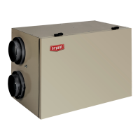
Explains the unit's function in exchanging indoor stale air with fresh outdoor air using a cross-flow core for heat transfer.

Installation Considerations

Equipment Inspection and Selection

Guides on inspecting the unit for damage after unpacking and selecting an appropriate installation location for accessibility and performance.

Component Description

Unit Installation

Mounting Procedures

Details methods for mounting the unit, including suspension from floor joists or installation on a shelf with vibration isolation.

System Application Types

Independent System Application

Describes applying the ERV/HRV as a standalone unit with separate registers for fresh air supply and stale air return throughout the home.

Forced-Air Application

Details integrating the ERV/HRV with existing forced-air systems, connecting supply and return to the ductwork for air exchange.

Ductwork and Connections

Connecting Ducts and Drains

Instructions for connecting flexible ducts, insulating them, and setting up the condensate drain with a loop trap.

Exterior Hood Installation

Guidance on locating and installing fresh-air intake and stale-air exhaust hoods, ensuring proper separation and height.

Wall Control

Control Types and Location

Lists available wall control options and recommends placing them in an area that monitors fresh air circulation.

Wiring

Operation

Humidity Control

Explains the humidity selector's function and recommends humidity levels to avoid condensation during different seasons.

OneTouch Control Function

Details the OneTouch control's ability to cycle through operation modes with button presses.

Operating with Evolution Control

Accessories

Timers

Details the use of 20-minute and 60-minute adjustable timers to override wall control for high-speed operation.

Electrical Connections

Balancing ERV;HRV

Balancing Procedure

Step-by-step guide for balancing airflow using a magnehelic gauge and balancing dampers to ensure optimal system performance.

Damper Adjustment and Recording

Instructions on adjusting fresh and exhaust air dampers and recording airflow information for future reference.

Ventilation Evaluation

Ventilator Sizing

Provides guidelines and tables based on ASHRAE standards to determine the required airflow for a home based on area and bedrooms.

Control Board Operation

Defrost and Mode Logic

Explains the control board's operation for defrost cycles and various air exchange modes (Off, Intermittent, High-Speed, Low-Speed).

Care and Maintenance

Unit Component Maintenance

Covers cleaning and maintenance for filters, blower motor, energy recovery core, and unit door access.

Troubleshooting

Override and Speed Tests

Details how to perform override tests for high and low speed operation, and adjusting blower speed settings.

Troubleshooting Guide and Error Codes

Connection Diagram

Logic Diagram

Overview

The ERV/HRV (Energy/Heat Recovery Ventilator) is a device designed to exchange indoor stale air with outside fresh air, while transferring both sensible and/or latent heat between the incoming fresh air and outgoing stale air. This cross-flow design core allows for heat and/or latent energy transfer without mixing the air streams. The unit operates at two airflows: 50 CFM (cubic feet per minute) in low speed and 100 CFM in high speed. It is available in both vertical and horizontal configurations.

Function Description:

The primary function of the ERV/HRV is to provide balanced ventilation, ensuring a continuous supply of fresh outdoor air while exhausting an equal amount of stale indoor air. This process helps maintain indoor air quality and comfort. The energy recovery core is a key component, transferring heat and/or latent energy between the two air streams. In heating mode, it recovers heat from the exhaust air to pre-warm the incoming fresh air. In cooling mode, it pre-cools and dehumidifies the incoming fresh air using the cooler, drier exhaust air. The unit also includes mechanical filters to trap dust and an electronic control circuit for proper operation.

Important Technical Specifications:

  • Airflow: 50 CFM (low speed), 100 CFM (high speed).
  • Configurations: Vertical and Horizontal.
  • Power Supply: 115VAC, 60Hz.
  • Control Board/Accessories Power: 12VDC.
  • Ducting: Insulated flexible ducts are required for connections to the exterior wall to prevent condensation. When connecting to a forced-air system, 18 inches (457mm) of flexible duct at ERV/HRV ports is recommended to act as a silencer.
  • Defrost Cycle: The unit continually monitors outside air temperature. If the outside air is at or below 23°F (-5°C), it initiates a defrost cycle by closing the outside air damper and recirculating warm indoor air through the heat recovery core. This process occurs every 32 minutes with a 6-minute defrost cycle. At 5°F (-15°C), it defrosts for 6 minutes every 32 minutes. At -17°F (-27°C), it defrosts for 6 minutes every 20 minutes.
  • Balancing: Airflow balancing is crucial for proper operation. This is achieved using a magnehelic gauge and balancing dampers at the fresh air intake and stale air exhaust ducts. The unit is considered balanced if there is a difference of ±10 CFM (or ±5 l/s or 17 m³/h) between the two airflows.

Usage Features:

  • Mounting: The unit can be suspended from floor joists using chains and springs, or installed on a shelf with an isolation pad to dampen vibration. It must always be installed as level as possible.
  • Application: Can be used as an independent or stand-alone unit, or in conjunction with a forced-air system. For forced-air applications, the fresh-air supply and stale-air return connect directly to the return-air duct system. The furnace or fan coil blower must be interlocked and operate continuously whenever the ERV/HRV is energized.
  • Wall Controls: Four remote wall control options are available: Basic Control, OneTouch Control, Standard Control (includes dehumidistat), and Latent Control (includes humidistat for ERVs only). These controls allow selection of various operating modes (Off, Low, High, Intermittent).
  • Integrated Control: All units have an integrated control located under the unit, in front of the electrical compartment. A push button on this control allows direct unit operation, overriding wall control functions. An LED indicates the current mode (Off, Intermittent, Low, High) and blinks to signal problems.
  • Timers: Optional push-button timers (20-minute) can override the wall control for high-speed operation in specific areas like bathrooms or kitchens. A 60-minute adjustable timer is also available for high-speed ventilation for a select amount of time.
  • Evolution Control System: The ERV/HRV can be controlled by the Evolution system control, which simultaneously manages the ERV/HRV and the indoor blower. It offers AUTO, LOW, and HIGH settings in both heating and cooling modes, and a DEHUM setting in heating mode.
  • Boot Sequence: After power loss or being unplugged, the unit performs a 30-second boot sequence, during which the integrated control LED lights GREEN or AMBER for 5 seconds, then shuts off for 2 seconds, and then lights RED while checking and resetting the motorized damper position.

Maintenance Features:

  • Filters: Washable filters should be cleaned every 3 months. Use a vacuum cleaner to remove heavy dust, then wash in lukewarm water and allow to dry completely before reinstalling. Do not clean filters in a dishwasher or dry them with a heating appliance.
  • Exterior Hoods: Regularly check and clean screens on exterior intake and exhaust hoods.
  • Blower Motor and Wheel: Blower motors are factory lubricated for life, so lubrication is not recommended. However, inspect and clean any accumulated dirt and grease annually.
  • Energy Recovery Core: The special energy recovery core should be vacuumed every 3 months to remove dust and dirt. The core should only be serviced when the outdoor temperature is 60°F to 75°F (16°C to 24°C) and it is dry. Do not use water to clean the core.
  • Door Removal: The ERV/HRV door can be removed by unlatching brief case style latches, then sliding it to the right and removing it from hinges. The door must be in place and secured shut for proper operation.
  • Troubleshooting: The manual provides a detailed troubleshooting guide based on integrated control LED flashes (GREEN for thermistor error, RED for open door/unplugged unit/exhaust motor error, AMBER for damper error) and common issues like unit not working, damper actuator failure, wall control issues, dehumidistat/timer problems, motor failures, and defrost cycle malfunctions. It also includes an override test function for high and low-speed operation.

Bryant ERVBBSVA1100 Specifications

General IconGeneral
BrandBryant
ModelERVBBSVA1100
CategoryFan
LanguageEnglish

Related product manuals