EasyManua.ls Logo

Bryant HRVBBLHA - User Manual

Bryant HRVBBLHA
24 pages
Print Icon
To Next Page IconTo Next Page
Loading...
1
Installation Instructions
HRVBBLHA
HRVBBSVU
HRVBBLVU
HEAT RECO VERY V ENTIL A TO R
A05260
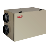
Fig. 1 --- HRVBBLHA Conventional Unit
A92268
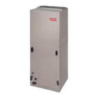
F i g . 2 --- H R V B B S V U C o m p a c t U n i t
A92377
Fig. 3 --- HRVBBLVU High Efficiency Unit
Note: Read the entire instruction manual before starting the
installation.
SAFETY CONSIDERATIONS
Installation and servicing of this equipment can be
hazardous due to mechanical and electrical components.
Only trained and qualified personnel should install, repair,
or service this equipment.
Untrained personnel can perform basic maintenance
functions such as cleaning and replacing air filters. All other
operations must be performed by trained service
personnel. When working on this equipment, observe
precautions in the literature, on tags, and on labels
attached to or shipped with the unit and other safety
precautions that may apply.
Follow all safety codes. Installation must be in compliance
with local and national building codes. Wear safety glasses,
protective clothing, and work gloves. Have fire extinguisher
available. Read these instructions thoroughly and follow all
warnings or cautions included in literature and attached to
the unit.
Recognize safety information. This is the safety--- alert symbol
!
!
When you see this symbol on the unit and in instructions or
manuals, be alert to the potential for personal
injury.Understand these signal words; DANGER,
W ARNING, and CAUTION. These words are used with the
safety ---alert symbol. DANGER identifies the most serious
hazards which will result in severe personal injury or death.
WARNING signifies hazards which could result in personal
injury or death. CAUTION is used to identify unsafe
practices which may result in minor personal injury or
product and property dam age. NOTE is used to highlight
suggestions which will result in enhanced installation,
reliability, or operation.
INTRODUCTION
The Heat Recovery Ventilator (HRV) is used to exchange
indoor stale air with outside fresh air. The HRV unit is
equipped with a special heat recovery core which transfers
sensible heat between the fresh incoming air and stale
exhaust air.
It is required to locate the HRV in a conditioned space.
Special attention should be given to condensate drain, duct
application, balancing HRV, and locating unit for easy
access and routine maintenance. The cross---flow design
core allows entering and leaving air streams to transfer heat
energy without mixing (See Fig. 14, and 17---24).
LOCATION
Step 1.—Inspect Equipment
Move carton to final installation location. Remove HRV from
carton taking care not to damage unit. Remove all
packaging and inspect unit for damage. Remove parts bag
from inside unit. File claim with shipping company if
shipment is damaged or incomplete. Check to make sure
HRV unit matches Fig. 1 through 3 and 4 through 6.

Other manuals for Bryant HRVBBLHA

Questions and Answers

Summary

HRV Installation Instructions

Safety Considerations

General safety precautions and warnings for installation and servicing.

Introduction to HRV

Explains the purpose and basic function of the Heat Recovery Ventilator.

Location Guidelines

Provides recommendations for optimal unit placement within a building.

Equipment Inspection Upon Receipt

Instructions for checking the unit for damage or completeness after unpacking.

Unit Installation Steps

Mounting the HRV Unit

Details on securely suspending and attaching the HRV unit using chains and springs.

Selecting the Installation Location

Guidelines for choosing the optimal placement for the HRV unit.

Connecting Ducts to the HRV

Steps for connecting fresh air and stale air ducts to the unit.

Condensate Drain and Wall Controls

Condensate Drain Connection

Instructions for properly connecting the unit's condensate drain line.

Wall Control Operation Modes

Describes operation of Basic, OneTouch, Standard, and Automatic wall control units.

Control Wiring and Humidity Features

Wall Control Wiring Details

Details on connecting the wall control to the HRV unit's circuit board.

Humidity Selector Function

Explains the role of the humidity selector in controlling indoor humidity.

Electrical Connections and Accessories

115-vac and 12-vdc Wiring

Covers both main power and low-voltage control wiring requirements.

Optional Timer Accessories

Instructions for connecting 20-minute and 60-minute adjustable timers.

Balancing Airflow Procedures

Balancing Damper Installation

Procedure for installing and adjusting balancing dampers for optimal airflow.

Flow Collar Airflow Measurement

Method for measuring airflow using flow collars and a magnehelic gauge.

Ventilation Requirements and Control Board Setup

Ventilation Calculation Methods

Two methods to determine approximate ventilation needs for a house.

Control Board Configuration

Guidance on setting up configuration jumpers on the electronic control board.

Defrost Cycle and Air Exchange Modes

Explains defrost logic and high/low-speed air exchange operations.

Care, Maintenance, and Troubleshooting

Component Maintenance Procedures

Instructions for cleaning and maintaining unit components like filters, motors, and core.

Troubleshooting Controls and Airflow

Steps to diagnose issues with controls, boards, airflow, and noise.

Error Signaling and System Reset

Interpreting error codes and procedures for resetting the HRV unit.

Wiring Diagrams

HRVBBLHA Wiring Diagram

Schematic showing electrical connections for HRVBBLHA models.

HRVBBSVU;HRVBBLVU Wiring Diagrams

Schematics for HRVBBSVU and HRVBBLVU models' electrical connections.

Dimensional Drawings

HRVBBLHA Unit Dimensions

Detailed measurements and port locations for the HRVBBLHA unit.

HRVBBSVU;HRVBBLVU Dimensions

Detailed measurements for HRVBBSVU and HRVBBLVU units.

HRVBBLVU Specific Dimensions

Detailed measurements for HRVBBLVU models.

Service Training Information

Packaged Service Training Programs

Details on available video-based training programs for product knowledge.

Classroom Service Training Programs

Information on hands-on classroom training for enhanced skills.

Overview

This document provides installation and operating instructions for the Bryant Heat Recovery Ventilator (HRV) models HRVBBLHA, HRVBBSVU, and HRVBBLVU. The HRV is designed to exchange indoor stale air with outside fresh air, utilizing a special heat recovery core to transfer sensible heat between the incoming fresh air and outgoing stale air.

Function Description:

The HRV's primary function is to provide ventilation by continuously exchanging indoor air with outdoor air while recovering heat. This helps maintain indoor air quality and humidity levels. The unit can operate in conjunction with a forced-air system or as an independent, stand-alone unit. In a forced-air application, the HRV's fresh-air supply and stale-air return connect directly to the return-air duct system, distributing fresh air throughout the building. The furnace or fan coil blower must be interlocked to operate continuously when the HRV is energized, ensuring proper air circulation. An integrated interlock relay within the control energizes the indoor equipment blower when the HRV is active.

The HRV features a cross-flow or counter-flow heat recovery core (depending on the model) that transfers heat between the two air streams without mixing them. Dampers are used in compact models to control air exchange with outdoor air during defrost mode. Mechanical filters trap dust from the air, and a condensation tray collects condensate from the heat recovery core.

Important Technical Specifications:

  • Power: Operates on 115 VAC. Comes with a power cord for plug-in to a fused outlet. Unit must be grounded.
  • Control Circuitry: The HRV circuit board, wall control, and accessories operate on 12 VDC.
  • Blower Motors: Two-speed operation (high and low speed). Three-speed blowers are factory connected to high and low-speed taps, but can be changed to medium speed.
  • Defrost Cycle: The HRV continuously monitors outside air temperature. If the temperature is at or below 23°F (-5°C), it initiates a defrost cycle. This involves closing the outside air damper and recirculating warm indoor air through the heat recovery core for a set duration (e.g., 6 minutes every 32 minutes at 5°F/-15°C, or 6 minutes every 20 minutes at -17°F/-27°C). The frequency and duration of the defrost cycle vary with outdoor temperature.
  • Ventilation Capacity: Defined by the greatest total airflow required, based on Canadian National Building Code 1995 and CSA F326.1 revision.
  • Ductwork: Insulated flexible duct is required for fresh-air inlet and exhaust-air outlet ducts connecting to the exterior wall to prevent condensation. When connecting to a return-air duct system, insulated flexible duct can be used, or approximately 18 inches of flexible duct should be used at HRV ports for metal or rigid duct applications. Balancing dampers are provided with HRVBBLHA units and are field-supplied for HRVBBSVU and HRVBBLVU units.

Usage Features:

  • Wall Controls: Four options are available: Basic, OneTouch, Standard, and Automatic.
    • Basic Control: 3-position slide switch for OFF, LOW, and HIGH speed continuous blower operation.
    • OneTouch Control: "Push" button to select High (maximum speed, continuous), Low (minimum speed, continuous), or Intermittent (minimum speed for 20 minutes per hour, off for 40 minutes). Power indicator light changes color to indicate mode.
    • Standard Control: 3 basic modes: OFF, LOW (continuous air exchange, blower speed varies with control satisfaction), and INTERMITTENT (high-speed air exchange, unit shuts down when control is satisfied). Includes an ON LED and an AIR EXCHANGE LED.
    • Automatic Control: Adjustable dehumidistat and push-button switch to cycle between 3 modes (Intermittent, Continuous, Circulation). Features 5 LEDs to indicate mode of operation and a maintenance light that illuminates every 3 months to indicate filter cleaning is needed.
  • Evolution Control: Offers four settings in heating mode (AUTO, LOW, HIGH, DEHUM) and three in cooling mode (AUTO, LOW, HIGH). AUTO mode adjusts speed based on indoor humidity and outdoor temperature, cycling on/off every 30 minutes.
  • Timers:
    • 20 Minute Timer: Push-button timer to override wall control and run HRV at high speed for 20 minutes. Up to 5 timers can be applied.
    • 60 Minute Adjustable Timer: Provides 10 to 60 minutes of high-speed ventilation.
  • Humidity Selector: A built-in dehumidistat on the wall control helps manage indoor humidity during winter months to prevent condensation.
  • Jumper Settings: Configuration jumpers on the electronic control board allow for precise setup of the HRV micro-controller, affecting defrost cycles and damper operation.

Maintenance Features:

  • Door Removal: The HRV door can be removed by unlatching brief-case style latches and sliding it to the right, then removing it from hinges.
  • Filter Cleaning: Filters are washable and should be cleaned every 3 months. Use a vacuum cleaner to remove heavy dust, then wash in lukewarm water. Allow to dry completely before reinstalling. Do not use a dishwasher or heating appliance for drying.
  • Blower Motor and Wheel: Blower motors are factory-lubricated for life. Inspect and clean any accumulated dirt and grease annually.
  • Core Cleaning: The heat recovery core should be washed once a year, particularly after the season of most intense use. Soak for 3 hours in warm water and mild soap, then rinse under a stream of water. Do not use hot water or strong detergents.
  • Exterior Hoods: Regularly check and clean screens on exterior intake and exhaust hoods.
  • Troubleshooting: The manual provides a troubleshooting chart for common symptoms, causes, and solutions, focusing on the wall control, electronic control board, and blower motor. It also includes a temperature/ohm relationship chart for thermistor checks.

Bryant HRVBBLHA Specifications

General IconGeneral
BrandBryant
ModelHRVBBLHA
CategoryFan
LanguageEnglish

Related product manuals