15
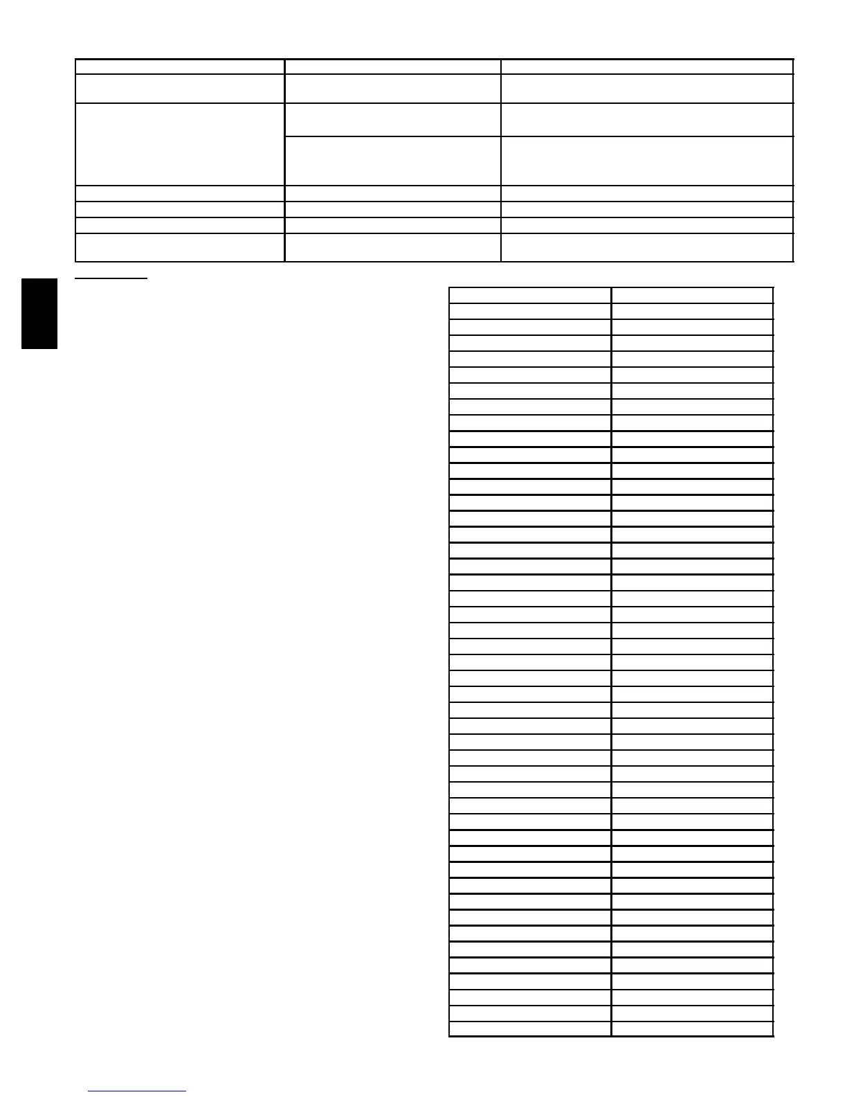
Table 6—Troubleshooting Chart
SYMPTOMS CAUSES SOLUTIONS
Air too humid
Continuous exchange mode
used in small houses
Use Intermittent Mode
Check humidity level settings
Unit not responding to wall control
Defrost condition is in effect
Outdoor temperature is below 23°F
Unit wil l operate when not in defrost mode.
Defrost cycle is based on outdoor ambient (See Table 10)
Broken control wire
Tes t w a ll c on t r o l
Check connections
Check thermistor
Unit stops momentarily Electrical supply interrupted
Check units circuit breaker
Air from distribution register too cold Improper calibration of air flow
Check calibration of flow rates
Unit makes annoying noise Ventilation wheel out of adjustment
Remove the motor and screw wheel on properly
Noise level too high at distribution
registerswheninhighspeed
Air duct system too short
Install a duct silencer
Override Test
To use override test function, a thermistor must be
connected to the control board. Unit must not be in defrost
mode during an override test.
HIGH SPEED
1. Disconnect HRV from 115vac.
1. Unplug wall control wires at control module terminal
block inside HRV.
2. Plug HRV back to 115vac.
3 . A t t a c h a w i r e a c r o s s J 3 --- 8 a n d J 3 --- 9 ( B a n d G ) o n
control module terminal block.
4. Push in door switch, this will initiate a high---speed
exchange.
LOW SPEED
1. Unplug HRV from 115vac.
2. Disconnect wall control wires at control module
terminal block inside HRV.
3. Plug HRV back to 115vac.
4. Connect a 3.0 K ohm resistor between J3 ---8 and J3---9
(B and G) on control module terminal block.
5. Push in door switch, this will initiate a low---speed
exchange.
4. Blower Speed Selection
Three---speed blowers are factory connected to electronic
control board on HIGH --- and LOW --- speed taps of blowers.
Installer can easily change low ---speed tap to
medium ---speed tap so electronic control will select
between high and medium speed. Connections can be
changed at motor location (See Table 8 and 9).
To change low speed to medium speed, proceed as
follows:
1. Unplug unit from 115vac.
2. Locate blower assembly.
3. L ocate red wire and blue wire coming from blower
assembly.
4. Unplug red wire f rom quick connect.
5. Unplug protecting cap quick connection from blue wire
and put on red wire coming from blower. The cap is a
safety insulator.
6. Connect red wire of main harness to blue wire.
7. Replace wires.
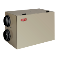
Table 7—Temperature/Ohm Relationship
TEMP F° OHMS
30 34,480
32 32,630
34 30,760
36 29,220
38 27,470
40 26,020
42 24,680
44 23,320
46 22,070
48 20,910
50 19,830
52 18,820
54 17,870
56 16,920
58 16,160
60 15,260
62 14,530
64 13,790
66 13,090
68 12,480
70 11,860
72 11,270
74 10,750
76 10,250
78 9,750
80 9,300
82 8,840
84 8,432
86 8,042
88 7,668
90 7,310
92 6,993
94 6,661
96 6,368
98 6,085
100 5,811
102 5,571
104 5,313
106 5,088
108 4,869
110 4,660
112 4,450
114 4,268
116 4,019
118 3,918
120 3,750
HRV