11
secure ducts. This procedure should be repeated to ensure
unit is balanced properly.
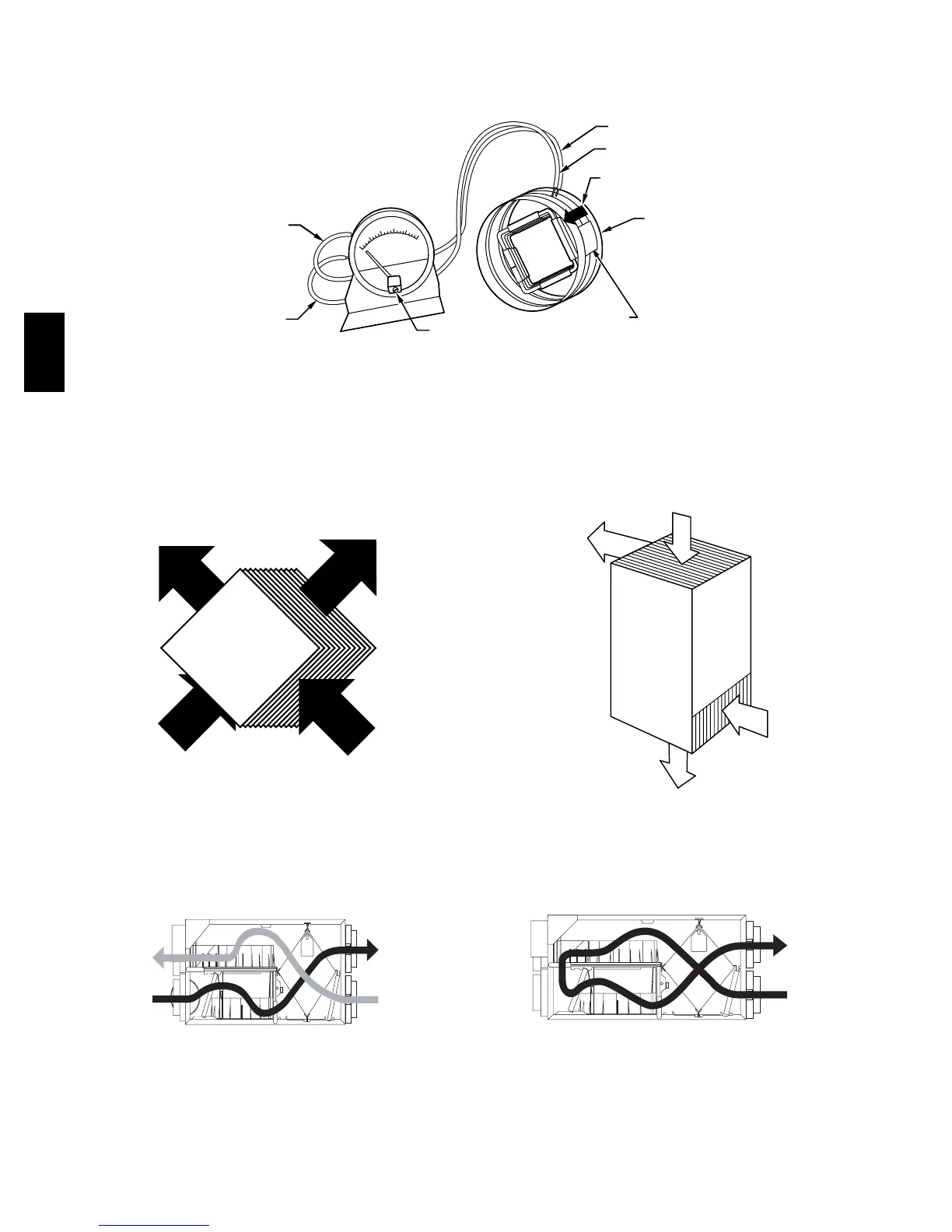
Note: The flow collar directional arrow (on flow collar) must
be oriented in the airflow direction of unit.
Note: Some field modification may be required to ensure
proper temporary installation of flow collar during balancing
when insulated flexible duct is used.
MAX
MIN
AIRFLOW
DIRECTION
CONVERSION
CHART
MAX
MIN
ZEROING SCREW
FLOW
COLLAR
A98400
Fig. 16 --- Magnehelic Gage
A05352
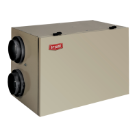
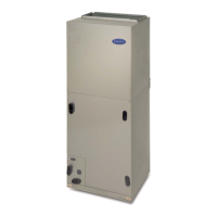
Fig. 17 --- HRVBBLHA and HRVBBSVU Cross Flow
STALE AIR
TO OUTSIDE
FRESH AIR
TO BUILDING
FRESH AIR
FROM OUTSIDE
STALE AIR
FROM BUILDING
A05353
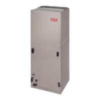
Fig. 18 --- HRVBBLHA Airflow During Air Exchange
STALE AIR
FROM BUILDING
22
o
C
72
o
F
FRESH AIR
TO BUILDING
20
o
C
68
o
F
STALE AIR
TO OUTSIDE
2
o
C
36
o
F
FRESH AIR
FROM OUTSIDE
0
o
C
32
o
F
A98404
F i g . 1 9 --- H R V B B LV U C o u n t e r f l o w
FILTERED AIR
TO BUILDING
STALE AIR
FROM BUILDING
A05354
Fig. 20 --- HRVBBLHA Airflow During Defrost
HRV