EasyManua.ls Logo

Bryant CAPVP series - User Manual

Bryant CAPVP series
4 pages
Print Icon
To Next Page IconTo Next Page
Loading...
CAPVP
Installation Instructions
Evaporator Coil
Upflow --- Downflow Cased
NOTE: Read the entire instruction manual before starting the
installation.
TABLE OF CONTENTS
PAGE
SAFETY CONSIDERATIONS 1.........................
INTRODUCTION 1...................................
INSTALLATION 2....................................
Inspect Equipment 2...............................
Select Installation 2................................
Installation of Evaporator Coils 2......................
Connect Refrigerant Piping 3.........................
Connect Lines 3...................................
Refrigerant Metering Device 4........................
Condensate Drain Line Connection 4...................
Waste Line Connection 4............................
SAFETY CONSIDERATIONS
Improper installation, adjustment, alteration, service, maintenance,
or use can cause explosion, fire, electrical shock or other conditions
which may cause death, personal injury or property damage.
Consult a qualified installer, service agency, or your distributor or
branch for information or assistance. The qualified installer or
agency must use factory--authorized kits or accessories when
modifying this product. Refer to the individual instructions
packaged with the kits or accessories when installing.
Follow all safety codes. Wear safety glasses, protective clothing
and work gloves. Use quenching cloths for brazing operations.
Have fire extinguisher available. Read these instructions
thoroughly and follow all warnings or cautions attached to the unit.
Consult local building codes and the current editions of the
National Electrical Codes (NEC) NFPA 70.
In Canada, refer to the current editions of the Canadian Electrical
Code CSA C22.1.
Recognize safety information. This is the safety-- alert symbol
.
When you see this symbol on the unit and in instructions or
manuals, be alert to the potential for personal injury.
Understand the signal words DANGER, WARNING and
CAUTION. These words are used with the safety--alert symbol.
DANGER identifies the most serious hazards which will result in
severe personal injury or death. WARNING signifies hazards
which could result in personal injury or death. CAUTION is used
to identify unsafe practices, which may result in minor personal
injury or product and property damage. NOTE is used to highlight
suggestions which will result in enhanced installation, reliability, or
operation.
ELECTRICAL SHOCK HAZARD
Failure to follow this warning could result in personal injury
or death.
Before installing or servicing system, always turn off main
power to system. There may be more than one disconnect
switch. Turn off accessory heater power if applicable. Lock out
and tag disconnect switch with a suitable warning label.
!
WARNING
EXPLOSION HAZARD
Failure to follow this warning could
result in death, serious personal injury,
and/or property damage.
Never use air or gases containing
oxygen for leak testing or operating
refrigerant compressors. Pressurized
mixtures of air or gases containing
oxygen can lead to an explosion.
!
WARNING
PERSONAL INJURY HAZARD
Failure to follow this caution may result in personal injury .
This coil contains Nitrogen precharge of up to 15 PSI. Release
of this pressure through the center of the rubber plugs is
required before removing the plugs.
CAUTION
!
CUT HAZARD
Failure to follow this caution may result in personal injury .
Sheet metal parts may have sharp edges or burrs. Use care and
wear appropriate protective clothing and gloves when
handling parts.
CAUTION
!
IMPORTANT: Nitrogen can leak out through the hole that the
needle pierced in the plugs. This does not indicate a leaking coil
nor warrant return of the coil.
Question and Answer IconNeed help?

Do you have a question about the Bryant CAPVP series and is the answer not in the manual?

Summary

General Safety Precautions

Electrical Shock Hazard

Warning regarding potential injury or death from electrical shock during installation or servicing.

Explosion Hazard

Warning about explosion risks from using air or gases containing oxygen for leak testing or operation.

Personal Injury Hazard

Caution that coil pressure release is required before removing plugs to avoid personal injury.

Cut Hazard

Caution about sharp edges on sheet metal parts and the need for protective gear.

Introduction

Installation

Inspect Equipment

File claim with shipper if equipment is damaged or incomplete.

Select Installation

Choose the correct installation method for your furnace type.

Upflow CAPVP Coil Installation

Set coil in place on upflow furnace discharge air opening and ensure level.

Downflow CAPVP Coil Installation

Install coil on supply duct opening, considering rotation and adapter needs.

Connect Refrigerant Piping

Connect refrigerant piping using specified line sizes and ensuring proper sealing.

Connect Refrigerant Liquid and Suction Lines

Unit or Property Damage Hazard

Take precautions to ensure aluminum tubes do not contact dissimilar metals to prevent galvanic corrosion.

Unit Damage Hazard (Brazing)

Wrap valve controls with heat-sinking material to prevent damage during brazing.

Personal Injury Hazard (Pressurization)

Warning to remove suction line plug first to depressurize the coil before removing liquid line plug.

Refrigerant Metering Device

Unit Damage Hazard (Tubing)

Do not bury more than 36" of tubing; ensure a 6" vertical rise to outdoor unit connections.

Condensate Line Connection

Property Damage Hazard (Pan)

Install a secondary condensate pan when installing over a finished ceiling or living area.

Condensate Drain to Waste Line

Install an open trap with an air gap when connecting the condensate line to a waste sewer line.

Waste Line Connection

Explosion Hazard

Provide trap with air gap in drain line when connecting to waste (sewer) line to prevent sewer gas escape.

Overview

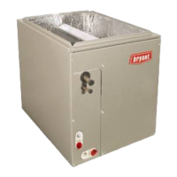
This document describes the installation and features of the CAPVP Evaporator Coil, designed for upflow and downflow cased applications. It serves as an installation guide for qualified installers and service agencies, emphasizing safety precautions and proper installation procedures.

Function Description:

The CAPVP Evaporator Coil is a key component in a heating, ventilation, and air conditioning (HVAC) system, specifically designed to work with multipoise furnaces. Its primary function is to facilitate heat exchange by evaporating refrigerant, thereby cooling the air that is then circulated throughout a building. The coil is enclosed within a casing, ensuring proper airflow and protection of its internal components. It is designed for use with R-410A refrigerant and includes a factory-installed hard shut-off TXV (Thermostatic Expansion Valve) for refrigerant metering.

Important Technical Specifications:

The CAPVP coils are available in various sizes, ranging from 1.5 to 5.0 tons, to accommodate different system capacities. The physical dimensions, particularly the flush fit to furnace width, vary by model:

  • 1.5, 2.0, 3.0 Ton (CAPVP1917ALA, CAPVP2517ALA, CAPVP3717ALA): 17-1/2" / 445 mm width.
  • 3.0, 3.5 Ton (CAPVP3721ALA, CAPVP4321ALA): 21" / 533 mm width.
  • 5.0 Ton (CAPVP6124ALA): 24-1/2" / 622 mm width.

All models utilize a 3/8" liquid line connection and varying suction line connections:

  • 3/4" suction line: For 1.5, 2.0, and 3.0 ton models (CAPVP1917ALA, CAPVP2517ALA, CAPVP3717ALA).
  • 7/8" suction line: For 3.0, 3.5, and 5.0 ton models (CAPVP3721ALA, CAPVP4321ALA, CAPVP6124ALA).

The coil is factory charged with 15 psi nitrogen, which must be released before installation. The TXV screen is located behind the liquid line plug. The refrigerant metering device (TXV) is factory-installed and non-adjustable, with preset superheat settings.

Usage Features:

  • Multipoise Compatibility: The CAPVP coil is designed for installation with multipoise furnaces, allowing for flexibility in system configuration (upflow or downflow).
  • Installation Flexibility:
    • Upflow: The coil is placed directly on the furnace's discharge air opening. It must be level to ensure proper condensate drainage.
    • Downflow: For downflow installations, especially when the coil is rotated 90° from the front of the furnace, a 3" (76 mm) field-supplied adapter may be required between the coil and the furnace. This adapter helps distribute airflow evenly across both coil slabs, preventing water blow-off or coil freeze-up, particularly in high-airflow situations.
    • Adapters for Width Discrepancies: If the coil width does not match the furnace width, field-fabricated adapters are necessary to bridge the gap.
  • Condensate Management: The coil features built-in condensate drain fittings, designed for PVC connections. Two 3/4" female threaded pipe connections are provided in each condensate pan. While a trap is not always necessary for the primary drain line, local codes may require one. If a trap is used, it should be at least 3" (76 mm) deep and no higher than the bottom of the unit's condensate drain opening. The condensate line should be pitched 1" (25.4 mm) for every 10 ft. of length towards an open drain or sump.
  • Secondary Condensate Pan (Optional/Recommended): For installations above finished ceilings or living areas, a field-fabricated secondary condensate pan under the entire unit is recommended to prevent property damage from overflow. A secondary condensate line from this pan should drain to a noticeable location, or a float switch can be installed to shut off the unit if the water level in the secondary pan becomes too high.
  • Horizontal Drain Connections: The unit is shipped with horizontal drain connections capped for vertical installations. For horizontal installations, these caps must be removed and placed on the vertical drain connections to maintain an airtight seal.
  • Refrigerant Piping: The coil uses refrigerant-grade tubing, with specific liquid and suction line sizes. It is crucial to use clean, undamaged tubing to prevent clogging of the refrigerant flow-control device.

Maintenance Features:

  • Leak Testing: After connecting refrigerant lines, leak checking is essential before insulating the suction line.
  • Nitrogen Purge: A 1/2 psig Nitrogen purge is required during brazing of refrigerant lines to prevent oxidation and contamination.
  • TXV Bulb Installation: The TXV bulb must be securely fastened in the indentation of the vapor line tube with full contact, using a hose clamp, and then re-wrapped with insulation.
  • Condensate Drain Maintenance: Regular testing of the primary drain line by slowly pouring water into the pan is recommended to check for leaks and ensure proper drainage. Traps, if installed, should be primed and insulated if located above a living area.
  • Air Gap for Waste Line Connection: If the condensate line connects to a waste (sewer) line, an open trap with an air gap must be installed ahead of the waste line to prevent sewer gases from entering the system.

Safety Considerations (Highlighted throughout the manual):

  • Electrical Shock Hazard: Always turn off and lock out main power before installing or servicing the system.
  • Explosion Hazard: Never use air or gases containing oxygen for leak testing or operating refrigerant compressors, as pressurized mixtures can lead to an explosion.
  • Personal Injury Hazard: Wear safety glasses, protective clothing, and work gloves. Use quenching cloths for brazing and have a fire extinguisher available.
  • Nitrogen Precharge: The coil contains 15 psi nitrogen. Release this pressure through the center of the rubber plugs before removing them.
  • Cut Hazard: Sheet metal parts may have sharp edges; use care and wear appropriate protective gear.
  • Unit/Property Damage Hazard:
    • Avoid direct contact or condensate run-off between aluminum tubes and dissimilar metals to prevent galvanic corrosion.
    • Wrap valves and nearby tubing with heat-sinking material (e.g., wet cloth) during brazing to prevent damage to the refrigerant control device.
    • Do not bury more than 36" (914 mm) of refrigerant tubing in the ground, and ensure a 6" (152 mm) vertical rise to the outdoor unit's valve connections if any tubing is buried, to prevent refrigerant migration and compressor damage.
    • Ensure proper condensate drainage to prevent water damage.
  • Codes and Standards: Follow all local building codes, current editions of the National Electrical Codes (NEC) NFPA 70, and in Canada, the Canadian Electrical Code CSA C22.1.

The manual emphasizes that improper installation, adjustment, alteration, service, maintenance, or use can lead to severe hazards, including death, personal injury, or property damage. It strongly advises consulting a qualified installer or service agency and using factory-authorized kits or accessories.

Bryant CAPVP series Specifications

General IconGeneral
BrandBryant
ModelCAPVP series
CategoryFan
LanguageEnglish

Related product manuals