17
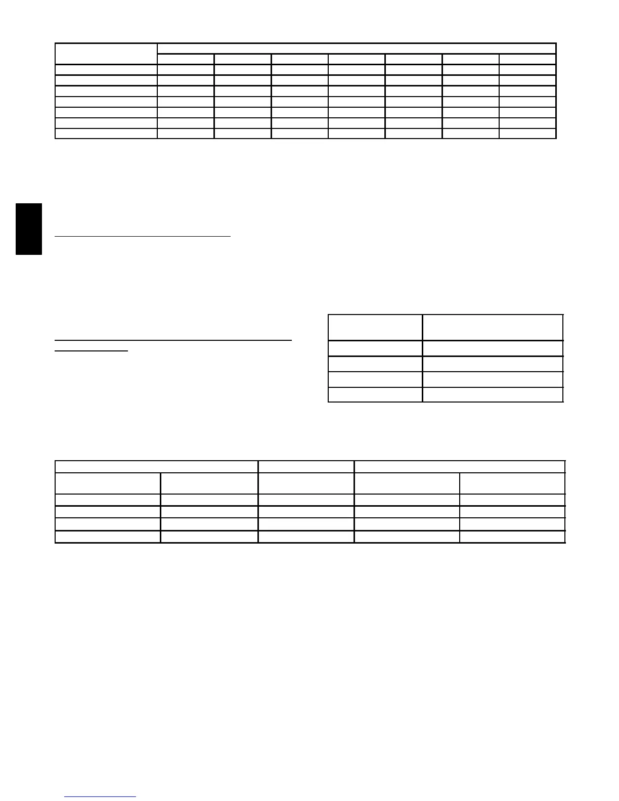
Ta b l e 1 3— Jumper Locations
MODEL
JUMPER TABLE
JU1A JU1B JU1C JU1D JU1E JU1F JU1G
HRVBBLHA1150 OUT OUT OUT OUT IN IN IN
HRVBBLHA1250 OUT OUT OUT OUT IN IN IN
HRVBBSVU1150 OUT OUT OUT OUT IN IN IN
HRVBBSVU1250 OUT OUT OUT OUT IN IN IN
HRVBBLVU1150 OUT OUT OUT OUT IN IN IN
HRVBBLVU1200 OUT OUT OUT OUT IN IN IN
HRVBBLVU1330 OUT OUT OUT OUT IN IN IN
7. Error Signaling
Two types of error can be signaled by the wall control
(automatic wall control only). In case of error, indicators on
wallcontrolwillflash.
When error occurs, set dehumidistat at 80 percent position.
This will enable you to properly troubleshoot problems.
Type 1—Loss of Memory (Auto Model
Only)
All indicators flash rapidly (rate of about once very sec).
When this occurs, reset power and check if problem still
exists. If indicators are still flashing, check red wire for
shorting on another component. If error still exists, wall
control has lost its memory. Replace wall control.
The defective wall control still works even when flashing, it
is working in backup mode. Original modes of wall control
arereplacedbybackupmode(SeeTable14).
Type 2—Communication Problem or Unsupported
Mode
(Auto Model
Only)
All indicators flashing at a rate of about once every 8 sec.
Communication is not properly entered or is not working.
CASE 1
User changes the mode on wall control and HRV does not
respond to command (OFF, LOW, or HIGH speed). Check
all wires to wall control particularly red wire (See Table 15).
CASE 2
User changes the mode but, HRV does not respond. All
indicators flash at a rate of about once every 8 sec. Check
all wires to wall control particularly green wire. If problem
still exists, test wall control with 5 ft of wire from HRV. If this
works, change wall control module inside HRV.
RESET
To reset HRV, proceed as follows:
1. Unplug HRV from 115vac.
2. Wait 15 sec.
3. Plug HRV into 115vac.
Tab le 14—Backup Mode
MODES
WALL CONTROL
BACKUP MODE
OFF OFF
1 INTERMITTENT
2 LOW---SPEED EXCHANGE
3 HIGH---SPEED EXCHANGE
Table 15—System Wiring Colors and Connections
CONTROL MODULE
WALL CONTROL WIRE
WALL CONTROL
Terminal Block No.
Ter m i n a l Blo ck
Identification
Color Ter m i nal No. Terminal Identification
J 3 --- 9 B Black
J 1 --- 4 B
J 3 --- 8 G
Green J 1 --- 3 G
J 3 --- 7 R
Red J 1 --- 2 R
J 3 --- 6 Y
Yellow J 1 --- 4 Y
HRV