13
120V, 60Hz
RETURN
120V, 60Hz
LINE
CPU
K2
K4
K5
J5-2
J10-1J10-2
Exhaust fan motor
Supply fan motor
J5-1
J5-3
J7-2
J7-1
J4-1
J4-3
J6-2
J6-1
K1
K3
K2
24V class
2
9.5V
class 2
120V
90V
68V
neutral
J9-1
J9-2
J9-3
J4-2
J9-4
Exhaust fan motor
capacitor
Supply fan motor
capacitor
J8-1
J8-2
J8-4
J8-5
K4
J12-2
J12-1
A1
A2
Damper motor
J3-2
J3-1
J2-2
J2-1
F1
J12-5
J12-4
J12-3
J2-3
J2-4
J2-5
Door interlock magnetic switch
J11-2
J11-1
K1
K3
K5
J14-3
J14-1
J14-2
AIR HANDLER
FAN INTERLOCK
24 VAC
CLASS 2 CIRCUIT ONLY
(optional; see notes 3, 5)
J14-4
J14-5
J14-6
J14-7
J14-8
J14-9
J14-10
Override
(optional; see notes 3, 4)
Field wiring wall control
(see notes 3, 4)
NC
LOGIC DIAGRAM
A07417
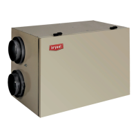
Fig. 18 -- ERV / HRV Wiring Diagram
Manufacturer reserves the right to disc ontinue, or change at any time, s pecifications or designs without notice and without inc urring obligations.
E2008 Bryant Heating & Cooling Systems D 7310 W. Morris St. D Indianapolis, IN 46231 Printed in U.S.A. Edition Date: 02/08
R e p l a c e s : I I E R V H R V --- 6 4 --- 1
Catalog No. IIER
HR
--- 6 4 --- 2
ERV / HRV
 Loading...