1
577E----A, 577E----E
PREFERREDt 15--16 SEER 2--STAGE PACKAGED AIR CONDITIONER AND
GAS FURNACE SYSTEM WITH PURONr (R--410A) REFRIGERANT
SINGLE AND THREE PHASE
2--5 NOMINAL TONS (SIZES 24--60)
Installation Instructions
IMPORTANT: Effective January 1, 2015, all split system and
packaged air conditioners must be installed pursuant to applicable
regional efficiency standards issued by the Department of Energy.
NOTE: Read the entire instruction manual before starting the
installation.
NOTE: Installer: Make sure the Owner’s Manual and Service
Instructions are left with the unit after installation.
TABLE OF CONTENTS
PAGE
SAFETY CONSIDERATIONS 1.........................
INTRODUCTION 2...................................
RECEIVING AND INSTALLATION 2--15.................
Check Equipment 2..................................
Identify Unit 2....................................
Inspect Shipment 2.................................
Provide Unit Support 2...............................
Roof Curb 2......................................
Slab Mount 3.....................................
Field Fabricate Ductwork 3............................
Provide Clearances 3.................................
Rig and Place Unit 3.................................
Inspection 3......................................
Rigging/Lifting of Unit 3............................
Connect Condensate Drain 11..........................
Install Flue Hood 11..................................
Install Gas Piping 12.................................
Install Duct Connections 13............................
Configuring Units for Downflow (Vertical)
Discharg e 13.....................................
Install Electrical Connections 14........................
High-- Voltage Connections 14........................
Special Procedures for 208--V Operation 14..............
Control Voltage Connections 14.......................
Standard Connection 15.............................
Heat Anticipator Setting 15..........................
Transformer Protection 15...........................
PRE-- S TART-- UP 15...................................
START--UP 16--31.....................................
Check for Refrigerant Leaks 16.........................
Start--Up Heating & Make Adjustments 16................
Check Heating Control 16...........................
Check Gas Input 17................................
Adjust Gas Input 17................................
Check Burner Flame 19.............................
Normal Operation 29...............................
Airflow and Temperature Rise 29......................
Heating Sequence of Operation 29.....................
Limit Switches 29.................................
Rollout Switch 29.................................
Start-- Up Cooling & Make Adjustments 29................
Checking Cooling Control Operation 29................
Checking & Adjusting Refrigerant Charge 30............
Indoor Airflow and Airflow Adjustments 30.............
Cooling Sequence of Operation 31.....................
MAINTENANCE 66--69................................
Air Filter 66......................................
Indoor Blower and Motor 66.........................
A09033
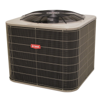
Fig. 1 -- Unit 577E
(Low NOx Model Available)
Induced Draft (Combustion Air) Blower 67..............
Flue Gas Passageways 67............................
Limit Switch 67...................................
Burner Ignition 67.................................
Main Burners 67...................................
Removal of Gas Train 67............................
Outdoor Coil, Indoor Coil, & Condensate Drain Pan 67....
Outdoor Fan 68...................................
Electrical Controls and Wiring 68.....................
Refrigerant Circuit 69...............................
Gas Input 69......................................
Evaporator Airflow 69..............................
Puron Items 69....................................
TROUBLESHOOTING 70..............................
START--UP CHECKLIST 70............................
SAFETY CONSIDERATIONS
Improper installation, adjustment, alteration, service maintenance,
or use can cause explosion, fire, electrical shock, or other
conditions which may cause death, personal injury, or property
damage. Consult a qualified installer, service agency, or your
distributor or branch for information or assistance. The qualified
installer or agency must use factory--authorized kits or accessories
when modifying this product. Refer to the individual instructions
packaged with the kits or accessories when installing.
Follow all safety codes. Wear safety glasses, protective clothing,
and work gloves. Have a fire extinguisher available. Read these
instructions thoroughly and follow all warnings or cautions
included in literature and attached to the unit. consult local
building codes, the current editions of the National Fuel Gas Code
(NFGC) NFPA 54/ANSI Z223.1, and the National Electrical Code
(NEC) NFPA 70.
In Canada refer to the current editions of the National Standards of
Canada CAN/CSA-- B149.1 and .2 Natural Gas and Propane
Installation codes, and Canadian Electrical Code CSA C22.1
Recognize safety information. This is the safety--alert symbol
.
When you see this symbol on the unit and in instructions or manu-
als, be alert to the potential for personal injury. Understand these
signal words: DANGER, WARNING, and CAUTION. These
words are u sed with the safety--alert symbol. DANGER identifies
the most serious hazards which will result in severe personal injury
or death. WARNING signifies hazards which could result in per-