224
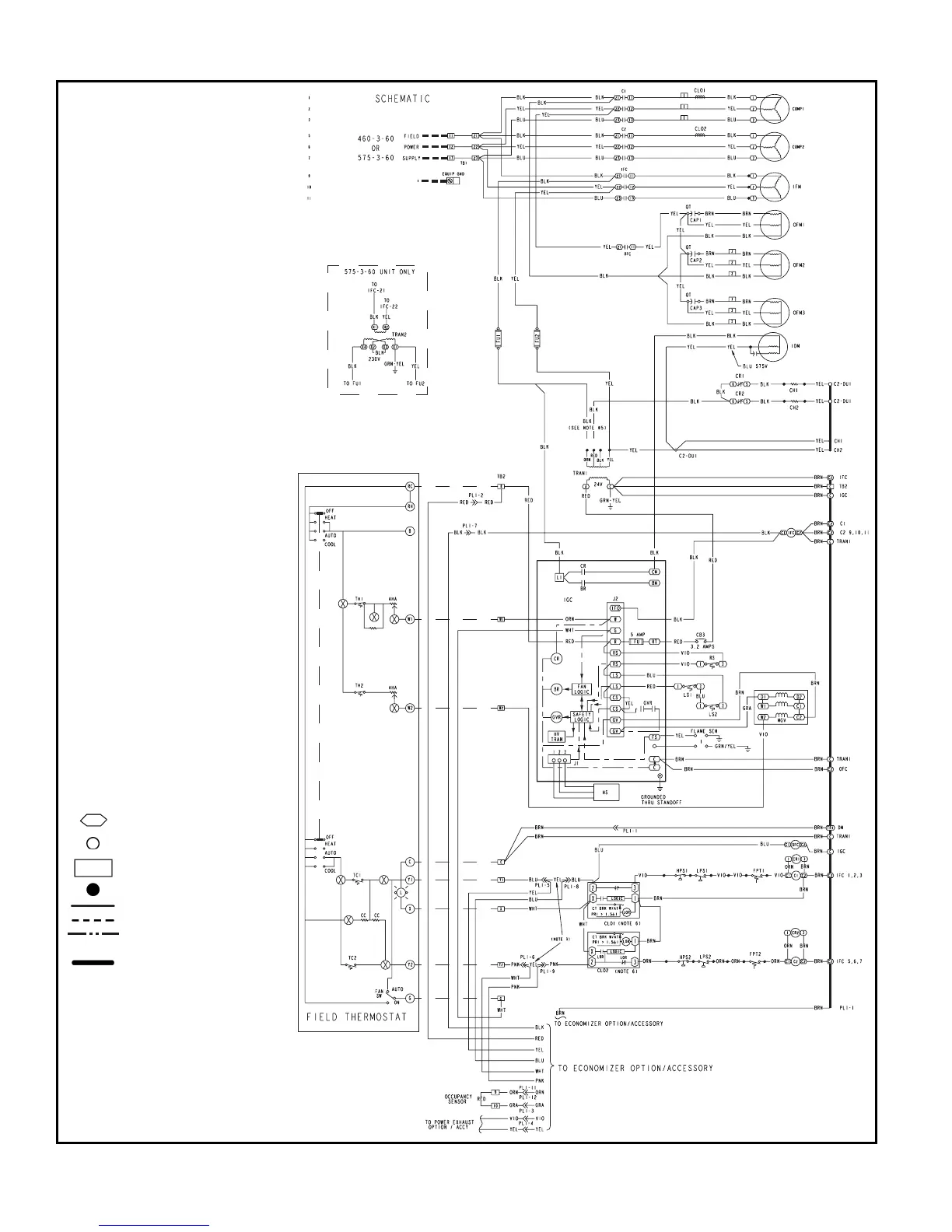
TYPICAL WIRING SCHEMATICS — 580F
Typical Wiring Schematic — 580F180, 460-3-60 Shown
LEGEND
AHA — Adjustable Heat Anticipator
C—Contactor, Compressor
CAP — Capacitor
CB — Circuit Breaker
CC — Cooling Compensator
CH — Crankcase Heater
CLO — Compressor Lockout
COMP — Compressor Motor
CR — Control Relay
DU — Dummy Terminal
EQUIP — Equipment
FPT — Freeze Protection
Thermostat
FU — Fuse
GND — Ground
HPS — High-Pressure Switch
HS — Hall Effect Sensor
HV — High Voltage
I—Ignitor
IDM — Induced-Draft Motor
IFC — Indoor-Fan Contactor
IFCB — Indoor-Fan Circuit Breaker
IFM — Indoor-Fan Motor
IGC — Integrated Gas Unit
Controller
L—Light
LOR — Lockout Relay
LPS — Low-Pressure Switch
LS — Limit Switch
MGV — Main Gas Valve
OFC — Outdoor-Fan Contactor
OFM — Outdoor-Fan Motor
PL — Plug Assembly
PRI — Primary
QT — Quadruple Terminal
R—Relay
RS — Rollout Switch
SEN — Sensor
SW — Switch
TB — Terminal Block
TC — Thermostat, Cooling
TH — Thermostat, Heating
TRAN — Transformer
Terminal (Marked)
Terminal (Unmarked)
Terminal Block
Splice
Factory Wiring
Field Wiring
Option/Accessory Wiring
To indicate common
potential only, not to
represent wiring.
a48-7461



 To Next Page