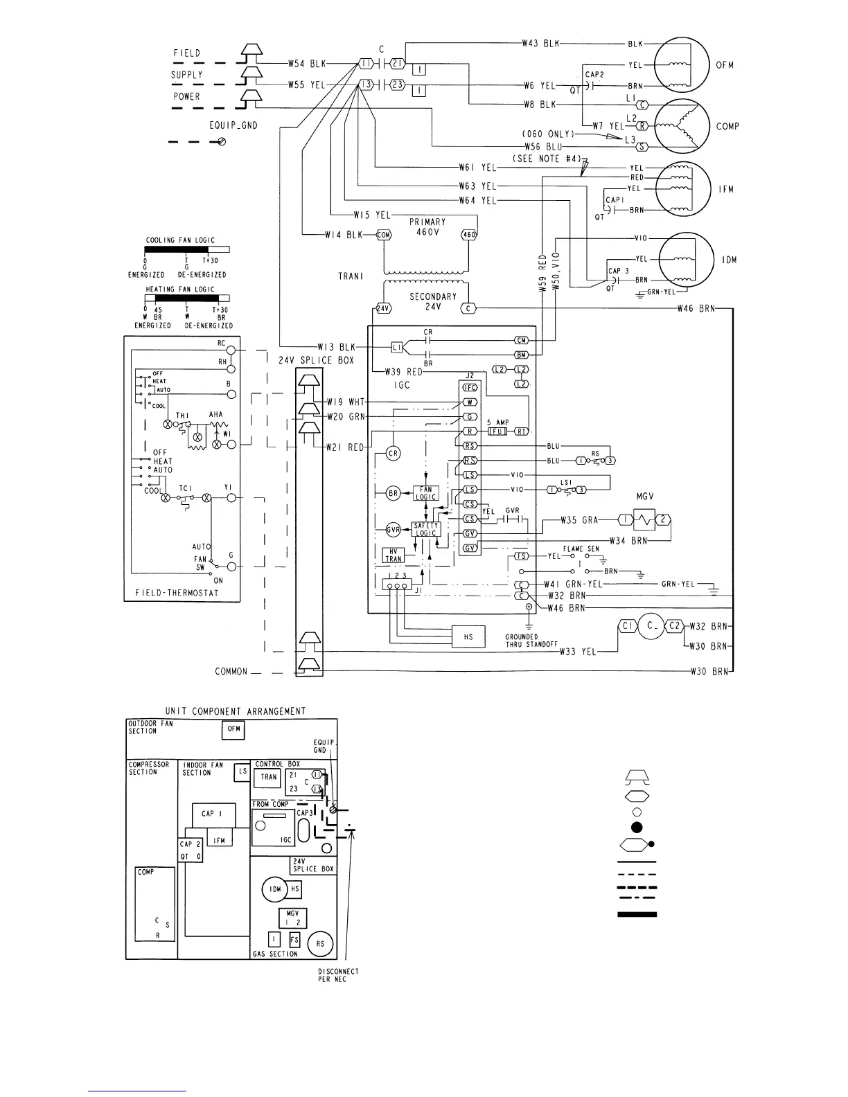
LEGEND
AHA — Adjustable Heat Anticipator
BR — Blower Relay
C—Contactor
CAP — Capacitor
COMP — Compressor Motor
CR — Combustion Relay
CS — Centrifugal Switch
EQUIP — Equipment
FS — Fusible Link
FU — Fuse
GND — Ground
GV — Gas Valve
GVR — Gas Valve Relay
HS — Hall Effect Sensor
HV — High Voltage
I—Ignitor
IDM — Induced-Draft Motor
IFC — Indoor-Fan Contactor
IFM — Indoor-Fan Motor
IGC — Integrated Gas Unit Controller
L1 — Line
LS — Limit Switch
LS1 — Limit Switch
MGV — Main Gas Valve
NEC — National Electrical Code
OFM — Outdoor-Fan Motor
QT — Quadruple Terminal
RS — Rollout Switch
SEN — Sensor
SW — Switch
TRAN — Transformer
Field Splice
Terminal (Marked)
Terminal (Unmarked)
Splice
Splice (Marked)
Factory Wiring
Field Control Wiring
Field Power Wiring
Accessory or Optional Wiring
To Indicate Common Potential
Only, Not to Represent Wiring
NOTES:
1. If any of the original wires furnished are replaced, they must be replaced with type 90 de-
gree C wire or its equivalent.
2. See price pages for thermostat and subbases.
3. Use 75 degree C copper conductors for field installation.
4. On all units for G.E. motors wire as follows: For high speed IFM, disconnect RED wire from
IGC:BM and connect BLK wire from IFM. For medium speed, disconnect RED wire from
IGC:BM and connect BLU wire from IFM.
Fig. 17 — 460-3-60 Wiring Diagram, Units 582A and 583A
—21—
 Loading...