2. Keep the outdoor fan operating for 15 minutes,
3. Display the appropriate error code on the status light (see
Table 9),
4. After a 15 minute delay, if Yl or Y2 inputs are on and the
LPS or HPS is reset, energize appropriate compressor
contactor, either low or high.
5. If LPS or HPS has not closed after a 15 minute delay, the
outdoor fan is turned off. If the open switch closes anytime
after the 15 minute delay, then resume operation on call for
Y1 and/or Y2.
J. MAJOR COMPONENTS
TWO-SPEED CONTROL
The two-speed control board controls the following functions:
- Low- and high-compressor contactor operation
- Outdoor fan motor operation
- Crankcase heater operation
- Compressor protection
- Pressure switch monitoring
- Time delays
FIELD CONNECTIONS
The two-speed control received 24vac low-voltage control system
inputs through the screw connections on the left side of the control
board.
TWO-SPEED COMPRESSOR
The two-speed compressor contains motor windings that provide
2-pole (3500 RPM) operation.
COMPRESSOR INTERNAL RELIEF
The compressor is protected by an internal pressure relief (IPR)
which relieves discharge gas into compressor shell when differen-
tial between suction and discharge pressures exceeds 525 psi. The
compressor is also protected by an internal overload attached to
motor windings.
COMPRESSOR CONTROL CONTACTORS
Low and high capacity contactor coils are 24 volts. The electronic
control board controls the operation of the low speed (C-L) and the
high speed (C-H) contactors.
K. TEMPERATURE THERMISTORS
Thermistors are electronic devices which sense temperature. As
the temperature increases, the resistance decreases. Thermistors
are used to sense outdoor ambient and coil temperature. Refer to
Fig. 11 for resistance values versus temperature.
If the outdoor ambient or coil thermistor should fail, a fault code
appears at two-speed control. The crankcase heater is turned on
during all off cycles.
IMPORTANT: Outdoor Air Thermistor Placement
Mount outdoor air thermistor underneath unit base pan lip on
control box side of the unit. Attach to base pan with adhesive tape.
IMPORTANT: If outdoor air thermistor is not properly placed
underneath base pan, unit may see nuisance thermistor out of range
faults.
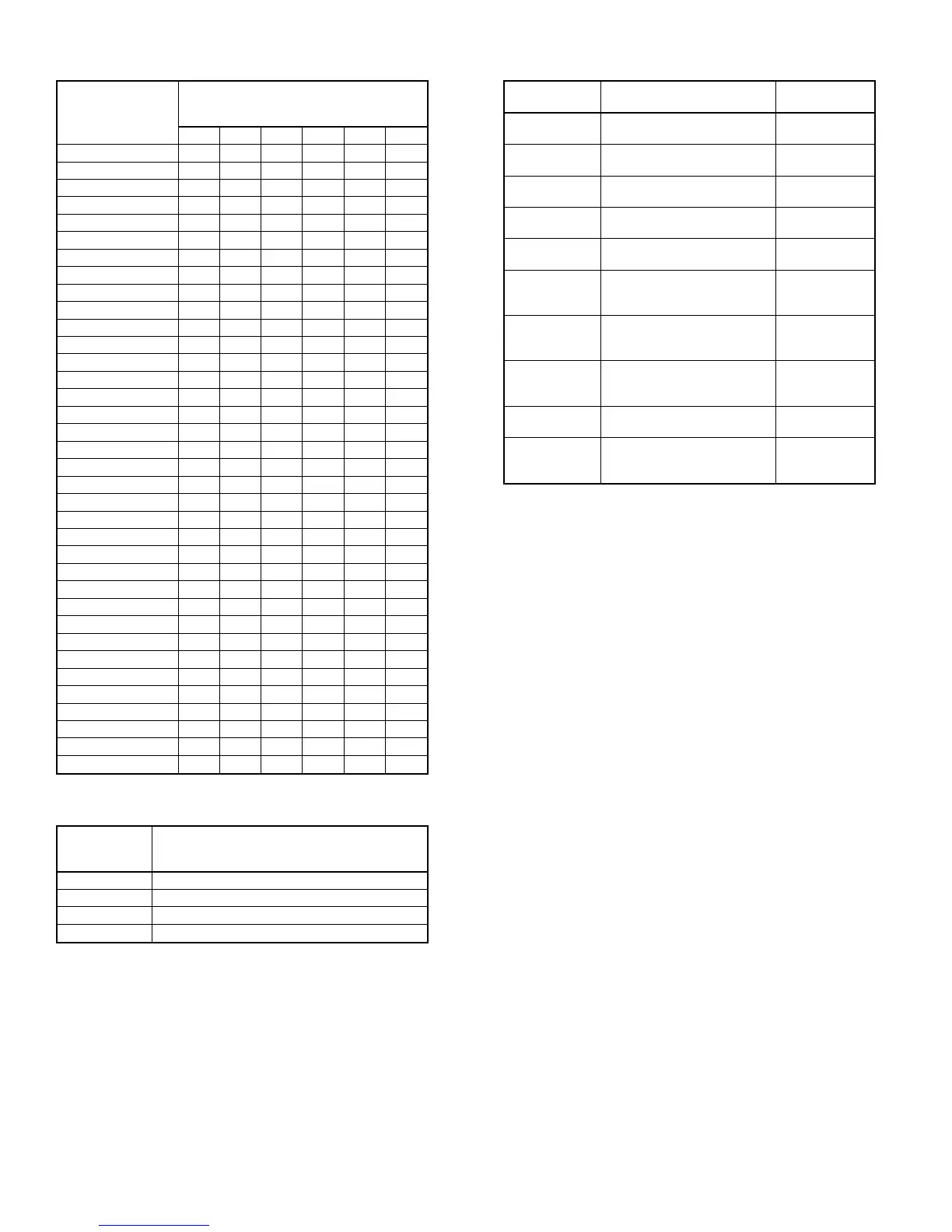
TABLE 7—REQUIRED LIQUID-LINE TEMPERATURE (°F)
LIQUID
PRESSURE AT
SERVICE VALVE
(PSIG)
REQUIRED SUBCOOLING
TEMPERATURE
(°F)
8 1012141618
189 58 56 54 52 50 48
195 60 58 56 54 52 50
202 62 60 58 56 54 52
208 64 62 60 58 56 54
215 66 64 62 60 58 56
222 68 66 64 62 60 58
229 70 68 66 64 62 60
236 72 70 68 66 64 62
243 74 72 70 68 66 64
251 76 74 72 70 68 66
259 78 76 74 72 70 68
266 80 78 76 74 72 70
274 82 80 78 76 74 72
283 84 82 80 78 76 74
291 86 84 82 80 78 76
299 88 86 84 82 80 78
308 90 88 86 84 82 80
317 92 90 88 86 84 82
326 94 92 90 88 86 84
335 96 94 92 90 88 86
345 98 96 94 92 90 88
354 100 98 96 94 92 90
364 102 100 98 96 94 92
374 104 102 100 98 96 94
384 106 104 102 100 98 96
395 108 106 104 102 100 98
406 110 108 106 104 102 100
416 112 110 108 106 104 102
427 114 112 110 108 106 104
439 116 114 112 110 108 106
450 118 116 114 112 110 108
462 120 118 116 114 112 110
474 122 120 118 116 114 112
486 124 122 120 118 116 114
499 126 124 122 120 118 116
511 128 126 124 122 120 118
TABLE 8
UNIT
TXV TYPE EXPANSION DEVICE
HIGH CAPACITY ONLY
SUBCOOLING AT SERVICE VALVE
024 14°F
036 15°F
048 12°F
060 16°F
TABLE 9—CONTROL FUNCTION LED CODE
CODE DEFINITION
SIGNAL
IMPORTANCE*
Constant flash
No pause
No demand
Stand by
10
1 flash
w/pause
Low-speed operation 9
2 flashes
w/pause
High-speed operation 8
3 flashes
w/pause
Outdoor thermistor failure 7
4 flashes
w/pause
Outdoor coil thermistor failure 6
3 flashes
pause
4 flashes
Thermistor out of range 5
5 flashes
pause
1 flash
Low pressure switch trip 4
5 flashes
pause
2 flashes
High pressure switch trip 3
6 flashes
w/pause
Compressor V
C
/V
H
trip 2
Constant light
No pause
No flash
Board failure 1
*Function light signal order of importance in case of multiple signal request; 1
is most important.
—16—
 Loading...