3. Size ductwork for cooling air quantity (cfm). The minimum
air quantity for proper electric heater operation is listed in
Tables 3 and 4. Heater limit switches may trip at air
quantities below those recommended.
4. Seal, insulate, and weatherproof all external ductwork. Seal,
insulate and cover with a vapor barrier all ductwork passing
through conditioned spaces. Follow latest Sheet Metal and
Air Conditioning Contractors National Association
(SMACNA) and Air Conditioning Contractors Association
(ACCA) minimum installation standards for residential
heating and air conditioning systems.
5. Secure all ducts to building structure. Flash, weatherproof,
and vibration-isolate duct openings in wall or roof accord-
ing to good construction practices.
A. CONVERTING HORIZONTAL DISCHARGE UNITS TO
DOWNFLOW (VERTICAL) DISCHARGE UNITS
WARNING: Before performing service or maintenance
operations on system, turn off main power to unit and
install lockout tag. Turn off accessory heater power
switch if applicable. Electrical shock could cause serious
injury or death.
1. Open all electrical disconnects and install lockout tag before
starting any service work.
2. Remove side duct covers to access bottom return and supply
knock outs.
NOTE: These panels are held in place with tabs similar to an
electrical knockout.
3. Use a screwdriver and hammer to remove the panels in the
bottom of the composite unit base.
4. Ensure the side duct covers are in place to block off the
horizontal air openings.
NOTE: Avoid abrupt duct size increases and reductions. Abrupt
change in duct size adversely affects air performance.
VI. PROVIDE FOR CONDENSATE DISPOSAL
NOTE: Ensure that condensate-water disposal methods comply
with local codes, restrictions, and practices.
The units dispose of condensate through a 3/4 in. NPT female
fitting that exits on the compressor end of the unit. Condensate
water can be drained directly onto the roof in rooftop installations
(where permitted) or onto a gravel apron in ground level installa-
tions. Install a field-supplied condensate trap at end of condensate
connection to ensure proper drainage. Make sure that the outlet of
the trap is at least 1 in. lower than the drain-pan condensate
connection to prevent the pan from overflowing. Prime the trap
with water. When using a gravel apron, make sure it slopes away
from the unit.
If the installation requires draining the condensate water away
from the unit, install a field-supplied 2-in. trap at the condensate
connection to ensure proper drainage. Condensate trap is available
as an accessory or is field-supplied. Make sure that the outlet of the
trap is at least 1 in. lower than the unit drain-pan condensate
connection to prevent the pan from overflowing. Connect a drain
trough using a minimum of field-supplied 3/4 -in. PVC or
field-supplied 3/4 -in. copper pipe at outlet end of the 2 -in. trap
(See Fig. 11). Do not undersize the tube. Pitch the drain trough
downward at a slope of at least 1 in. every 10 ft. of horizontal run.
Be sure to check the drain trough for leaks. Prime the trap at the
beginning of the cooling season start-up.
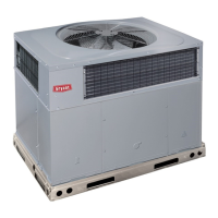
Fig. 6—Unit Leveling Tolerances
C99065
A
B
C
MAXIMUM ALLOWABLE
DIFFERENCE (in.)
A-B B-C A-C
1/4 1/4 1/4
Fig. 7—Slab Mounting Detail
C99096
OPTIONAL
RETURN
AIR
OPENING
OPTIONAL
SUPPLY
AIR
OPENING
EVAP. COIL COND. COIL
2"
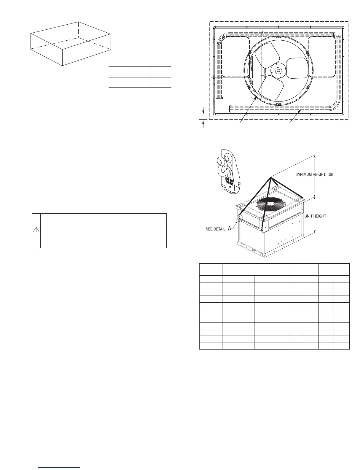
Fig. 8—Suggested Rigging
UNIT
MAXIMUM WEIGHT
(INCLUDES SHIPPING SKID)
AB
Size lb kg in. mm. in. mm.
601A030 309 140.2 19.5 495.3 17.50 444.5
601A036 313 142.0 19.5 495.3 17.75 450.9
601A042 345 156.4 19.5 495.3 17.75 450.9
601A048 375 170.1 20.5 520.7 20.62 523.8
601A060 440 199.6 19.5 495.3 19.75 501.7
602A030 342 155.2 20.0 508 19.25 489
602A036 350 158.8 20.0 508 19.0 482.6
602A042 372 168.8 21.0 533.4 20.5 520.7
602A048 377 171.0 20.0 508 21.25 539.8
602A060 450 204.2 21.0 533.4 20.0 508.0
A05179
DETAIL A
—7—
 Loading...