• Sleep Mode — The Sleep mode timer turns the unit off when
the timer reaches zero minutes. The durations that can be
selected are 1, 2, 3 or 7 hours. After the initial 30 minutes,
the user set point shifts approximately 1° F warmer. This
sequence repeats itself every 40 minutes up to a total of
150 minutes. When Sleep mode is enabled, the display on
the remote controller is dimmed.
• On/Off Timer Mode — The on/off timer will turn the unit
on or off at a user selectable on and off time (this is one
time event only). The unit will start in the same mode and
at the same selected temperature as when the system shut
off. If the room temperature is not within approximately
5° F of the set point 40 minutes before start-up, the unit
runs before the user selected on time is reached to achieve
the set point temperature at start-up.
• Automatic Operation Mode for Cooling Only Systems (538A
and 538S) — The unit samples the air in the room. Based
on the room temperature, the unit selects one of the fol-
lowing modes:
1. Cooling Mode — If the room temperature is more than
82.4 F with a preset temperature of 78.8 F.
2. Dry Mode — If the room temperature is more than
75.2 F and less than 82.4 F with a preset temperature
of 77 F.
3. Fan Only Mode — If the room temperature is less than
75.2 F.
The preset temperature can be changed by ±4° F using the
remote control.
• Automatic Operation Mode for Heat Pump Systems (538D)
— The operation mode will be determined after 20 seconds
of room monitoring (to determine the room temperature
and the outdoor air temperature).
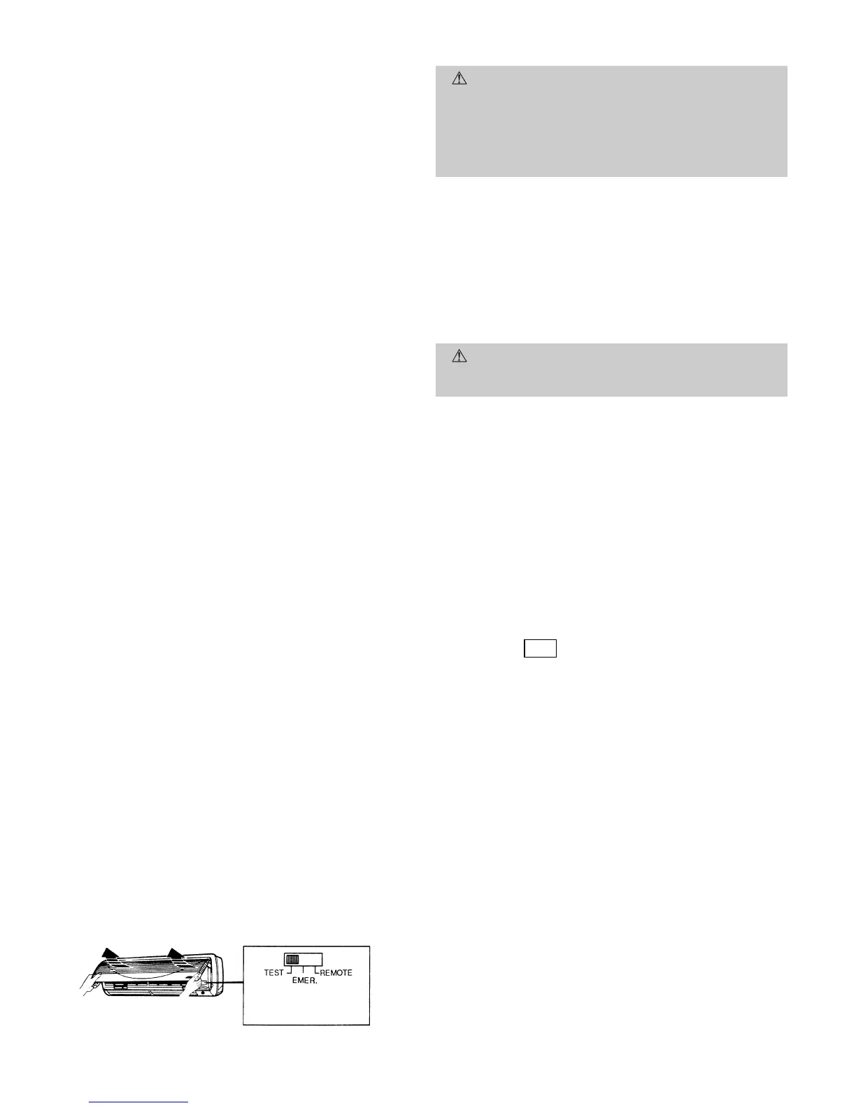
• Test Mode — The Test mode can be selected by setting the
slide switch on the fan coil unit to TEST position. The slide
switch is located on the front of the unit as shown in
Fig. 21. The fan coil unit will start immediately (there is
no compressor time delay when using Test mode) in Cool-
ing mode with an infinitely low set point. The indoor fan
speed will be at the high setting, and the swing louvers
will be on (moving up and down).
NOTE: The unit cannot be controlled by the remote controller
until the slide switch is returned to the REMOTE position.
• Emergency Mode — This mode is only to be used if the re-
mote controller is lost, damaged, or the batteries are dis-
charged. To initiate Emergency mode, manually move the
slide switch on the fan coil unit to the EMER position
(Fig. 21). The unit is automatically operated in Cooling or
Heating (538D units only) mode according to room tem-
perature. Emergency operation settings are as follows:
1. Operation mode: AUTO.
2. Fan Speed: AUTO.
3. Cooling set point: 77 F
4. Timer Mode: Continuous
NOTE: The unit cannot be controlled by the remote control-
ler until the slide switch is returned to the REMOTE
position.
CLEANING AND MAINTENANCE
CAUTION:
To avoid the possibility of electric shock,
before performing any cleaning and maintenance op-
erations, always turn off power to the system by press-
ing the orange ON/OFF button on the remote control-
ler. Turn off the outdoor disconnect switch located near
the outdoor unit. If the indoor unit is on a separate switch,
be sure it is also disconnected.
For proper system operation, perform the cleaning and main-
tenance operations in Table 8.
I. LUBRICATION
The indoor-fan automatic air sweep motor, and the outdoor-
fan motor are factory lubricated and require no oiling.
II. TO INSTALL OR REPLACE REMOTE CONTROLLER
BATTERIES
CAUTION:
Do not drop the remote controller — dam-
age to the device may result. Avoid getting the control-
ler wet.
NOTE: Before replacing the batteries, note that the remote
controller signal can be affected if electronic fluorescent lights
are installed nearby. The batteries may not need to be re-
placed. If you suspect this is the problem, consult your
local distributor.
Batteries should be replaced once a year. Use 2 batteries
(1.5 v, dc-type, AAA alkaline batteries). Never use old or re-
charged batteries together with new ones.
To replace batteries:
1. Slide the battery cover off from the back of the remote
controller. See Fig. 22.
2. Insert the 2 batteries in accordance with the markings
on the remote controller, so that the poles are correct
(+ and −).
RST
3. Press the button using an instrument screw-
driver or similar small, pointed tool.
4. Replace the cover securely.
It is time to replace the remote controller batteries when the
remote controller function becomes irregular, or the system
no longer responds to commands given close to the unit.
When shutting down the system for an extended period of
time, it is advisable to remove the batteries.
Consult distributor if any other equipment is turned on or
shows signs of disrupted operation if you use the wireless re-
mote controller, or if the system is turned on or shows signs
of disrupted operation when the remote controller of any other
equipment is used.
EMER — Emergency Mode
Fig. 21 — Slide Switch
—16—
 Loading...