Table 3 — High Wall Unit Package Contents
ITEM QUANTITY
Unit Mounting Template 1
Unit Mounting Bracket 1
1-in. Lag Screws for Unit Mounting 8
Hollow Wall Anchor Bolts for Unit Mounting 5
Wall Sleeve with Wall Cap 1
Infrared Wireless Remote Control Assembly 1
AAA Batteries (for remote control) 2
Remote Control Mounting Bracket 1
3
⁄
8
-in. Lag Screws for Remote Mounting Bracket 2
35 ft High Voltage Power Wiring (2-wire with ground) 1
35 ft Low Voltage Thermistor Wiring (3-wire) 1
AccuRaterT Body and Piston (018 and 024 cooling only units)* 1
Biflow Filter Drier 1
Owner’s Manual 1
Installation Instructions 1
Warranty Registration Card 1
*For heat pumps: additional heating AccuRater body and piston shipped with outdoor unit.
III. STEP 3 — MOUNT MOUNTING BRACKET ON WALL
1. Decide how refrigerant will be piped. If necessary, knock
out the appropriate pre-punched holes (Fig. 4) on unit
for piping and electrical connections.
2. Remove bracket from fan coil unit by pulling it down
from fan coil unit bottom as shown in Fig. 6.
3. Using a carpenter’s level, fasten mounting brackets into
the studs in the wall at least 10 in. away from the ceil-
ing with the 8 screws provided. Always be sure to insert
screws into the top 2 holes indicated in Fig. 6. Make sure
the attached bracket will support a 200 lb vertical load.
For a masonry wall, anchor shields can be used to at-
tach bracket to the wall.
4. Temporarily hang unit on bracket to check location and
level.
CAUTION:
If mounting bracket is not mounted level,
the indoor section will be mounted unevenly, and con-
densate drainage water may drip onto the floor. Also, a
gap between the bracket and the wall may result in vi-
bration and noise from the indoor section.
5. Mark and cut condensate and piping holes.
a. For piping through the wall, mark the wall below the
condensate connection and cut a 2
1
⁄
2
-in. hole into the
wall at either point ‘‘A’’ or point ‘‘B’’ in Fig. 7.
NOTE: The 2
1
⁄
2
-in hole must be made at a downward slope
to ensure proper condensate drainage. See Fig. 8. Slope con-
densate line at a minimum pitch of
1
⁄
4
in. per foot of line. The
condensate line cannot be run up for upper piping
connections − only refrigerant lines may be run up.
b. Push the wall sleeve (factory supplied with the unit)
through the 2
1
⁄
2
-in. wall opening.
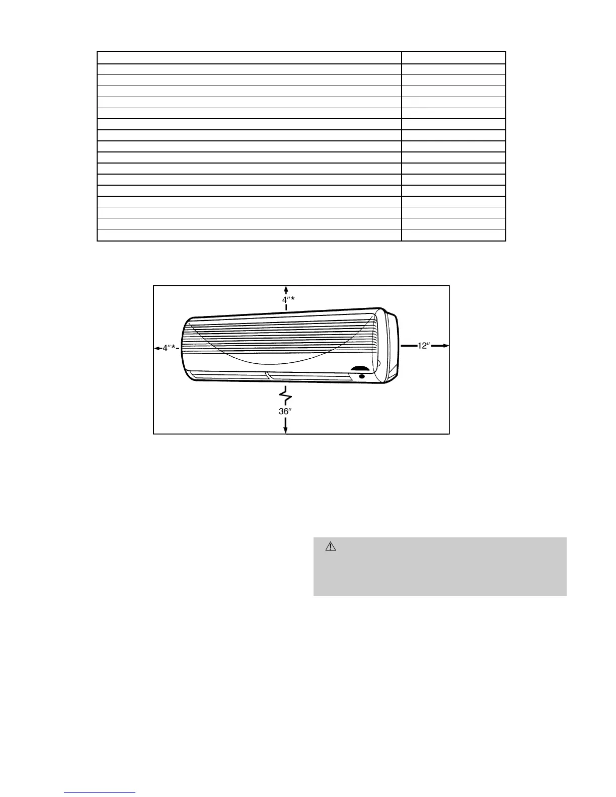
*A clearance of 49 is the absolute minimum. A clearance of 109 is
recommended.
NOTE: Remove unit front cover for control box access.
Fig. 3 — Minimum Required Clearances
—4—