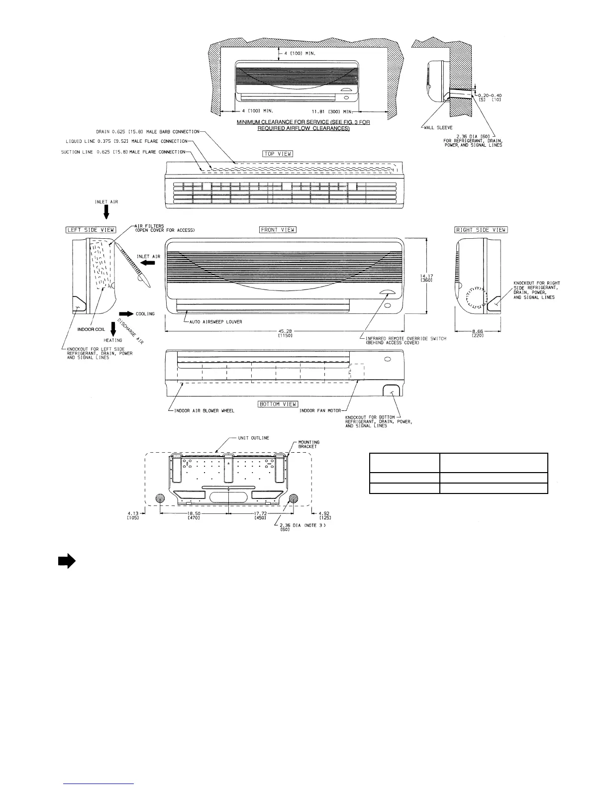
1. Dimensions in ( ) are in millimeters.
2. Direction of airflow.
3. Refrigerant, drain, and power connections may be made in unit
rear, bottom, left side, or right side.
4. Refrigerant is metered by AccuRaterT device in the fan coil unit
on 538A and 538D applications. A thermostatic expansion valve
is used in the outdoor unit on 538S applications. Insulate both
refrigerant lines on 538S and 538D applications.
5. The 49 top and left side clearances are absolute minimums. Clear-
ances of 109 are recommended.
6. Do not insert a trap in condensate drain line. The drain is inter-
nally trapped.
Fig. 2 — 619E Dimensional Drawing
UNIT
619E
WEIGHT
018 39 Lb (17.5 Kg)
024 43 Lb (19.5 Kg)
—3—