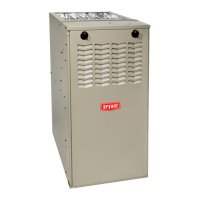
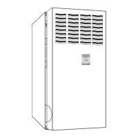
810SA/811SA: Installation, Start–Up, Operating and Service and Maintenance Instructions
Manufacturer reserves the right to change, at any time, specifications and designs without notice and without obligations.
29
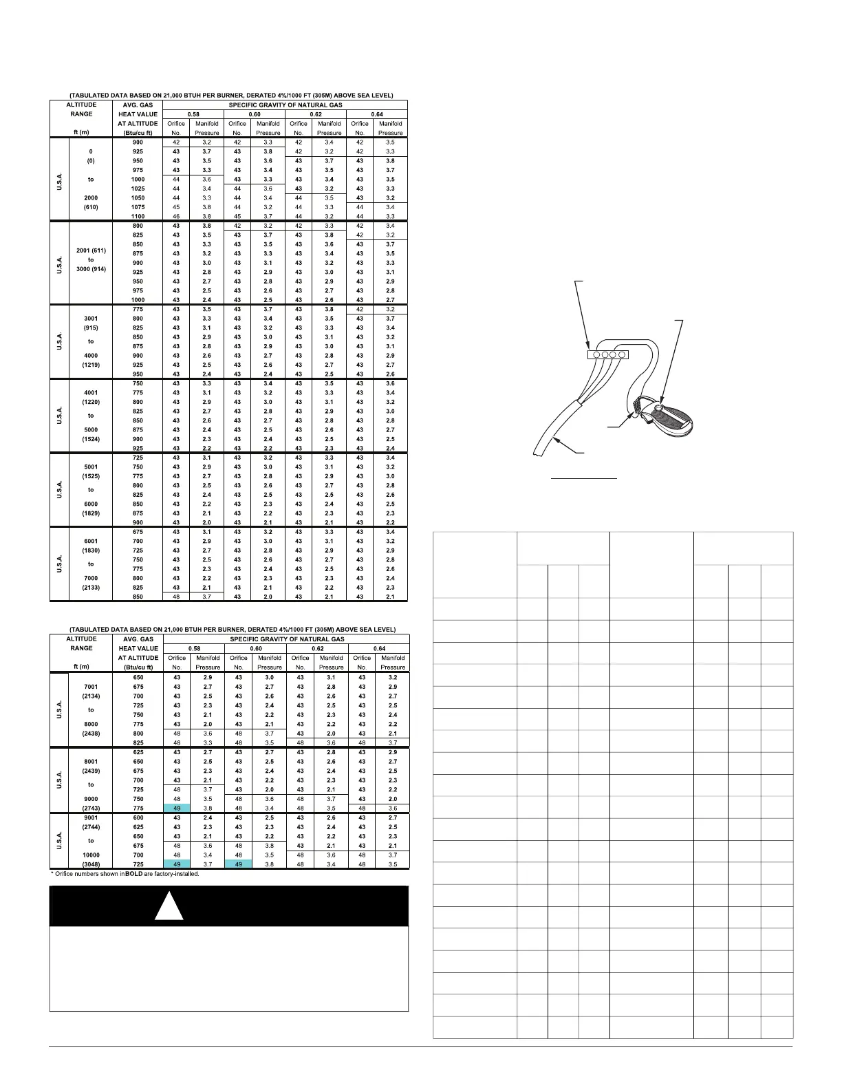
Table 12 – Orifice Size* And Manifold Pressure (In. W.C.) For Gas
Input Rate
A10181
A10181a
6. Set thermostat heat anticipator.
a. Mechanical thermostat - Set thermostat heat anticipator to match
the amp. draw of the electrical components in the R-W circuit.
Accurate amp. draw readings can be obtained at the wires
normally connected to thermostat subbase terminals, R and W.
The thermostat anticipator should NOT be in the circuit while
measuring current.
(1.) Remove thermostat from subbase or from wall.
(2.) Connect an amp. meter as shown in Fig. 46 across the R and
W subbase terminals or R and W wires at wall.
(3.) Record amp. draw across terminals when furnace is in
heating and after blower starts.
(4.) Set heat anticipator on thermostat per thermostat
instructions and install on subbase or wall.
b. Electronic thermostat: Set cycle rate for 4 cycles per hr.
A96316
Fig. 46 – Amp. Draw Check with Ammeter
WARNING
!
FURNACE OVERHEATING HAZARD
Failure to follow this caution may result in reduced furnace life.
Recheck temperature rise. It must be within limits specified on the
rating plate. Recommended operation is at the mid-point of rise range
or slightly above.
Table 13 – Gas Rate (Cu Ft./Hr.)
SECONDS
FOR 1
REVOLUTION
SIZE OF TEST
DIAL
SECONDS
FOR 1
REVOLUTION
SIZE OF TEST
DIAL
1 Cu
Ft.
2 Cu
Ft.
5 Cu
Ft.
1 Cu
Ft.
2 Cu
Ft.
5 Cu
Ft.
10 360 720 1800 50 72 144 360
11 327 655 1636 51 71 141 355
12 300 600 1500 52 69 138 346
13 277 555 1385 53 68 136 340
14 257 514 1286 54 67 133 333
15 240 480 1200 55 65 131 327
16 225 450 1125 56 64 129 321
17 212 424 1059 57 63 126 316
18 200 400 1000 58 62 124 310
19 189 379 947 59 61 122 305
20 180 360 900 60 60 120 300
21 171 343 857 62 58 116 290
22 164 327 818 64 56 112 281
23 157 313 783 66 54 109 273
24 150 300 750 68 53 106 265
25 144 288 720 70 51 103 257
26 138 277 692 72 50 100 250
27 133 267 667 74 48 97 243
28 129 257 643 76 47 95 237
29 124 248 621 78 46 92 231
R Y W G
10 TURNS
THERMOSTAT SUBBASE
TERMINALS WITH
THERMOSTAT REMOVED
(ANITICIPATOR, CLOCK, ETC.,
MUST BE OUT OF CIRCUIT.)
HOOK-AROUND
AMMETER
EXAMPLE:
5.0 AMPS ON AMMETER
10 TURNS AROUND JAWS
=
0.5 AMPS FOR THERMOSTAT
ANTICIPATOR SETTING
FROM UNIT 24-V
CONTROL TERMINALS