986TC: Installation, Start-up, Operating, Service and Maintenance Instructions
Manufacturer reserves the right to change, at any time, specifications and designs without notice and without obligations.
34
A05091
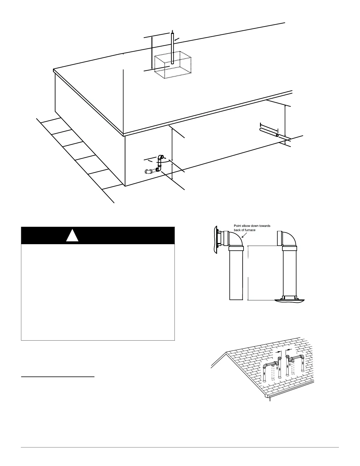
Fig. 43 – Vent Pipe Termination for Non-Direct Vent and Ventilated Combustion Air System
Direct Vent / 2-Pipe System
Direct vent (2-pipe) vent and combustion air pipes must terminate
outside the structure. See Fig. 46 For references to vent clearances
required by National code authorities. Allowable vent and combustion
air terminations are shown in Fig. 42.
Ventilated Combustion Air
The vent pipe for a Ventilated Combustion Air System must terminate
outdoors. See Fig. 47 for references to vent clearances required by
National code authorities. Allowable vent terminations are shown in
Fig. 43. The combustion air pipe terminates in a well-ventilated attic or
crawl space. Follow the clearances as shown in Fig. 52.
The combustion air pipe cannot terminate in attics or crawl spaces that
use ventilation fans designed to operate in the heating season. If
ventilation fans are present in these areas, the combustion air pipe must
terminate outdoors as a Direct Vent System.
A13406
Fig. 44 – Combustion Air Pipe Attachment
A96128
Fig. 45 – Pipe Vent and Combustion
Abandoned masonry
used as raceway
(per code)
12 in. (305 mm) min. from
overhang or roof
Maintain 12 in. (305mm)
minimum clearance
above highest anticipated
snow level or grade
whichever is greater.
Side wall termination
with 2 elbows (preferred)
12 in. min. (305 mm)from
overhang or roof
Maintain 12 in. (305mm)
minimum clearance
above highest anticipated
snow level or grade
whichever is greater
6 in. (152mm) minimum clearance
between wall and end of vent pipe.
10 in. (254mm) maximum pipe length
Sidewall Termination
with Straight Pipe (preferred)
Roof Termination (Preferred)
Vent
Maintain 12 in .
minimum clearance
above highest anticipated
snow level maximum of
24 in. (610mm) above roof.
90°
(305mm)
WARNING
!
CARBON MONOXIDE POISONING HAZARD
Failure to follow the instructions outlined below for each appliance
being placed into operation could result in carbon monoxide poisoning
or death.
For all venting configurations for this appliance and other gas
appliances placed into operation for the structure, provisions for
adequate combustion, ventilation, and dilution air must be provided in
accordance with:
U.S.A. Installations: Section 9.3 of the current edition of NFPA
54/ANSI Z223.1 Air for Combustion and Ventilation and applicable
provisions of the local building codes.
Canadian Installations: Part 8 of the current edition of
CAN/CSA-B149.1. Venting Systems and Air Supply for Appliances
and all authorities having jurisdiction.
12" (256mm) minimum
to
60”(1524 mm) or
1 additional elbow maximum
CASING SIDE OR TOP ATTACHMENT
COMBUSTION AIR PIPE
(NON-DIRECT VENT FOR ALL MODELS EXCEPT MODULATING UNLESS
INSTALLED IN ATTIC OR CRAWL SPACE)