986TC: Installation, Start-up, Operating, Service and Maintenance Instructions
Manufacturer reserves the right to change, at any time, specifications and designs without notice and without obligations.
70
A11326B
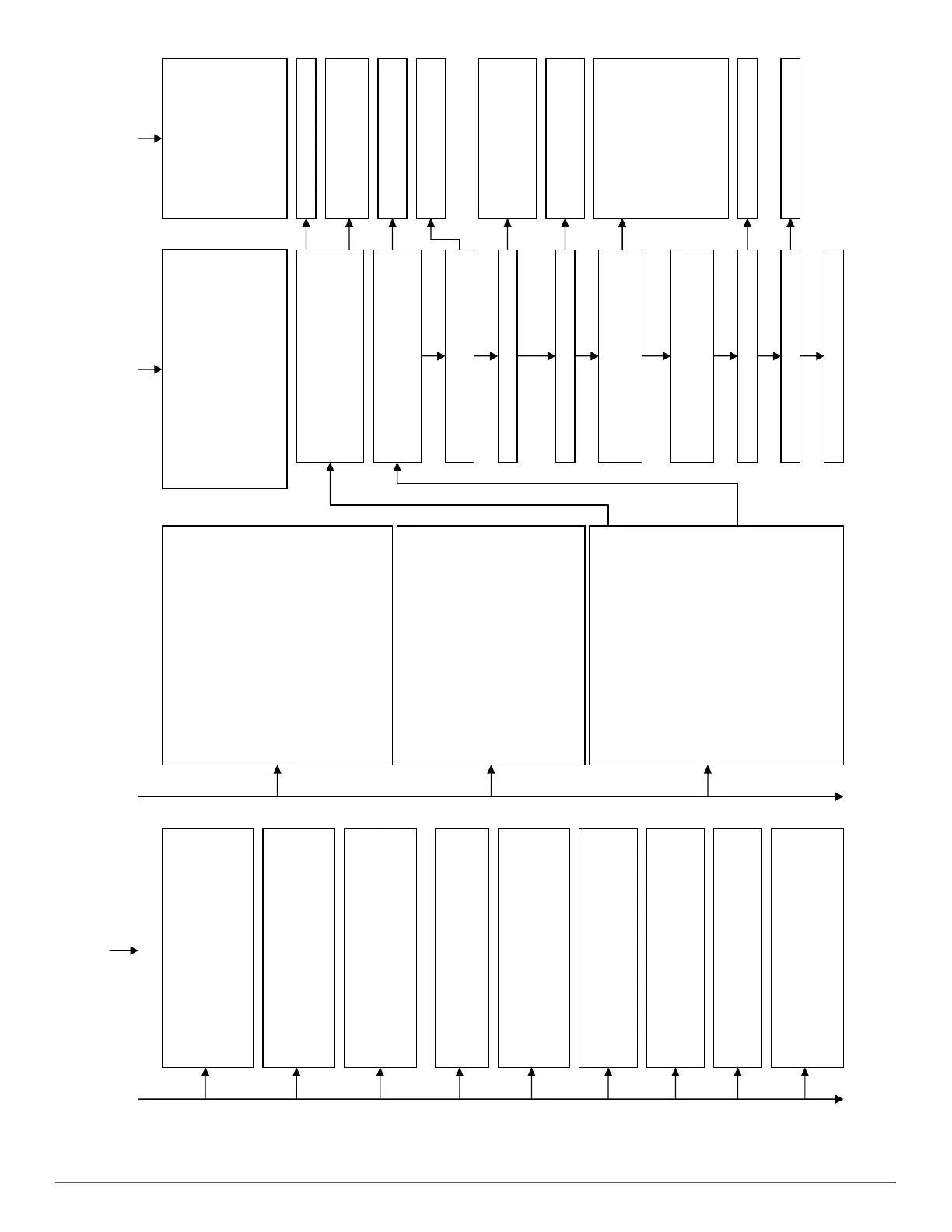
Troubleshooting Guide (Continued)
11 NO PREVIOUS CODE – Status codes are
erased after 72 hours or can be manually
erased by putting setup switch SW1-1 in
the ON position and jumpering R, W/W1,
and Y/ Y2 simultaneously until status code
#11 is flashed. Run system through a low-
heat, high-heat, or cooling cycle to check
system.
12 BLOWER ON AFTER POWER UP –
(115V OR 24V) – Normal operation.
Blower runs for 90 seconds, if unit is
powered up during a call for heat (R-
W/W1 closed) or when (R-W/W1 opens)
during the blower on-delay period.
13 LIMIT CIRCUIT LOCKOUT – Lockout
occurs if the limit or flame rollout switch is
open longer than 3 minutes or 10
successive limit trips occurred during high-
heat. Control will auto-reset after 3 hours.
Se e c o d e 3 3 .
14 IGNITION LOCKOUT – Syst em f ai led t o
ignite gas and prove flame in 4 attempts.
Control will auto-reset after 3 hours. See
st at us code 34.
21 GASHEATING LOCKOUT – Turn off
power and wait 5 minutes to retry. Check
for:
- Stuck closed gas valve relay on control.
-Miswireorshorttogasvalvewire.
22 ABNORMAL FLAME-PROVING SIGNAL
Flame is proved while gas valve is de-
energized. Inducer will run until fault is
cleared. Check for:
-Stucko
en or leak
as valve.
23 PRESSURESWITCH DID NOTOPEN–
Ch ec k f o r :
- Obstructed pressure tube.
- Pressure switch stuck closed.
24 SECON DARY VOLTA GE FUSE I S OPEN
Ch ec k f o r :
- Short circuit in secondary voltage (24V)
wiring including thermostat leads.
Disconnect thermostat leads to isolate
sho rt ci rcui t.
32 LOW-HEAT PRESSURESWITCHDID
NOT CLOSE OR REOPENED – If open
longer than 5 minutes, inducer shuts off
for 15 minutes before retry. If opens
during blower on-delay period, blower will
come on for t he selected blower off -delay.
Ch ec k f o r :
-Properventsizing.
- Air leak between vestibule and blower
compartment .
-Lowinletgaspressure(ifLGPSused).
- Restricted vent.
- Disconnected or obstructed pressure
tubing.
- Defective or miswi red pressure swit ches
-Excessivewind.
-Pluggedcondensatedrain.
-W
ater in vent piping, possible sagging
pipe.
- Defective inducer motor.
-Lowinducervoltage(115V)
33 LIMIT CIRCUIT FAULT – Indicates t he
limit or a flame rollout switch is open or the
furnace is operating in high-heat only
mode due to 2 successive low-heat limit
trips. Blower will run for 4 min. or until
open switch remakes whichever is longer.
If open longer t han 3 min., code changes
to lockout #13. If open less than 3 min.
status code #33 continues to flash until
blower shuts off. Flame rollout switch
requires manual reset. Check for:
- Loose blower wheel.
- Defective switch or connections.
-Improperlow-orh
igh-heat gas input
adjustment.
- Improper limit switch or no limit gasket.
- Dirty filter or restricted duct system.
34 IGNITION PROVING FAILURE– Ifflame is
not sensed during the trial for ignition
period, the control will repeat the ignition
sequence 3 more times before lockout #14
occurs. Ifflame signal is lost during the
blower on-delay period, blower will come on
for t he select ed blower off-delay. Check
the following itemsfirst before proceeding
to the next step.
-Gasvalveturnedoff.
- Manual shut-off valve.
-GREEN/ YELLOW wire MUST b e
connected to furnace sheet metal.
- Flame sensor must not be grounded.
To d et erm in e w he
ther the problem isin the
gas valve, igniter, or flame sensor the
systemcanbeoperatedincomponenttest
mode. To check the igniter remove the R
thermostat connection from the control,
reset power, and put setup switch SW1-6 in
the ON position to start the component test.
Does the igniter glow orange/white by the
end of the 15 second warm-up period?
Unplug igniter harness from control and
repeat component test by turning setup
swit ch SW1-6 OFF and t hen back ON.
Ch ec k f o r 1 1 5V b e t w e en p i n 3 an d
NEUTRAL-L2 on t he cont rol . Was 115V
present for t he 15 second period?
Check connections and retry.
If current is near typical value
(4.0-6.0 nominal) and burners
will not stay on, repeat check
in high-heat. If burners will
st il l n ot st ay on r epl ac e
cont rol. If burners operate i n
high-heat then switch to low-
heat, check manifold
pressure. If OK, check
burner carryover and flame
sensor l ocat i on.
Clean flame sensor with fi ne steel wool
and recheck current. Nominal current is
4.0 to 6.0 microamps.
Is current near t ypical value? Replace electrode.
Will main burners ignite and stay on? Replace furnace cont rol.
Fi xe d.
NO
YES
YES
YES
NO
NO
15 BLOWER MOTOR LOCKOUT – Indicates
the blower failed to reach 250 RPM or the
blower failed to communicate within 30
seconds after being turned ON in two
successive heating cycles. Control will
auto-resetafter3hours. Seecode41.
45 CONTROL CIRCUITRY
LOCKOUT Aut o-reset
after 1 hour lockout due
to:
-Flamecircuitfailure.
-Gasvalverelaystuck
open.
- Software check error.
Re s e t p o w e r t o c l e a r
lockout. Replace control
if code repeats.
Replace furnace control.
Check for continuity in the
harness and igniter. Replace
defective component.
Reconnect the Rthermostat lead and set
thermostat to call for heat. Connect
voltmeter across gas valve connections.
Does gas valve receive 24V?
Does gas valve open and allow gas to
flow?
Do the main burnersignite?
Do the main burners stay on?
Allow blower to come on and
repeat test to check for
intermittent operation.
Ch ec k t h a t al l g as v al v e s ar e
turned on. Replace valve.
Ch ec k co n n e ct i o n s. If OK,
replace control.
Ch ec k f o r :
- Inadequate flame carryover
or rough ignition.
-Lowinletgaspressure.
- Proper firing rate.
Re p e a t c a l l f o r h e a t a n d c h e c k f l a m e
sensor cu rrent du ri ng t ri al f or i g ni t i on
period. Is the DC microamps below 0.5?
YES
YES
YES
YES
YES
NO
NO
NO
NO
NO
NO
43 LOW-HEAT PRESSURESWITCHOPEN
WHILE HIGH-HEAT PRESSURE
SWITCH IS CLOSED- Checkfor:
- Low-heat pressure switch stuck open.
- Disconnected or obstructed pressure
tube.
- Miswired pressure switches.
-Lowinletgaspressure(ifLGPSused).
-Pluggedcondensatedrain.
- Water in vent piping, possible sagging
pipe.