—15—
Table 8 — Outdoor Air Damper Leakage
Table 9 — Return Air Pressure Drop (in. wg)
B. EconoMi$erIV Standard Sensors
Outdoor Air Temperature (OAT) Sensor
The outdoor air temperature sensor (HH57AC074) is a 10 to
20 mA device used to measure the outdoor-air temperature.
The outdoor-air temperature is used to determine when the
EconoMi$erIV can be used for free cooling. The sensor must
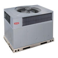
be field-relocated. See Fig. 24. The operating range of tem-
perature measurement is 40 to 100 F.
Supply Air Temperature (SAT) Sensor
The supply air temperature sensor is a 3 K thermistor
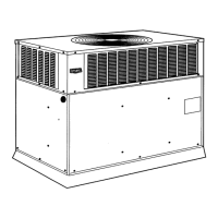
located at the inlet of the indoor fan. See Fig. 25. This sensor
is factory installed. The operating range of temperature
measurement is 0° to 158 F. See Table 10 for sensor tempera-
ture/resistance values.
The temperature sensor looks like an eyelet terminal with
wires running to it. The sensor is located in the “crimp end”
and is sealed from moisture.
Low Temperature Compressor Lockout Switch
The EconoMi$erIV is equipped with an ambient tempera-
ture lockout switch located in the outdoor airstream which is
used to lock out the compressors below a 42 F ambient tem-
perature. See Fig. 24.
Table 10 — Supply Air Sensor Temperature/
Resistance Values
DAMPER STATIC PRESSURE (in. wg)
0.2 0.4 0.6 0.8 1.0 1.2
LEAKAGE (cfm) 35 53 65 75 90 102
CFM
4500 5000 5400 6000 7200 7500 9000 10,000 11,250
0.040 0.050 0.060 0.070 0.090 0.100 0.110 0.120 0.140
TEMPERATURE (F) RESISTANCE (ohms)
–58 200,250
–40 100,680
–22 53,010
–4 29,091
14 16,590
32 9,795
50 5,970
68 3,747
77 3,000
86 2,416
104 1,597
122 1,080
140 746
158 525
176 376
185 321
194 274
212 203
230 153
248 116
257 102
266 89
284 70
302 55
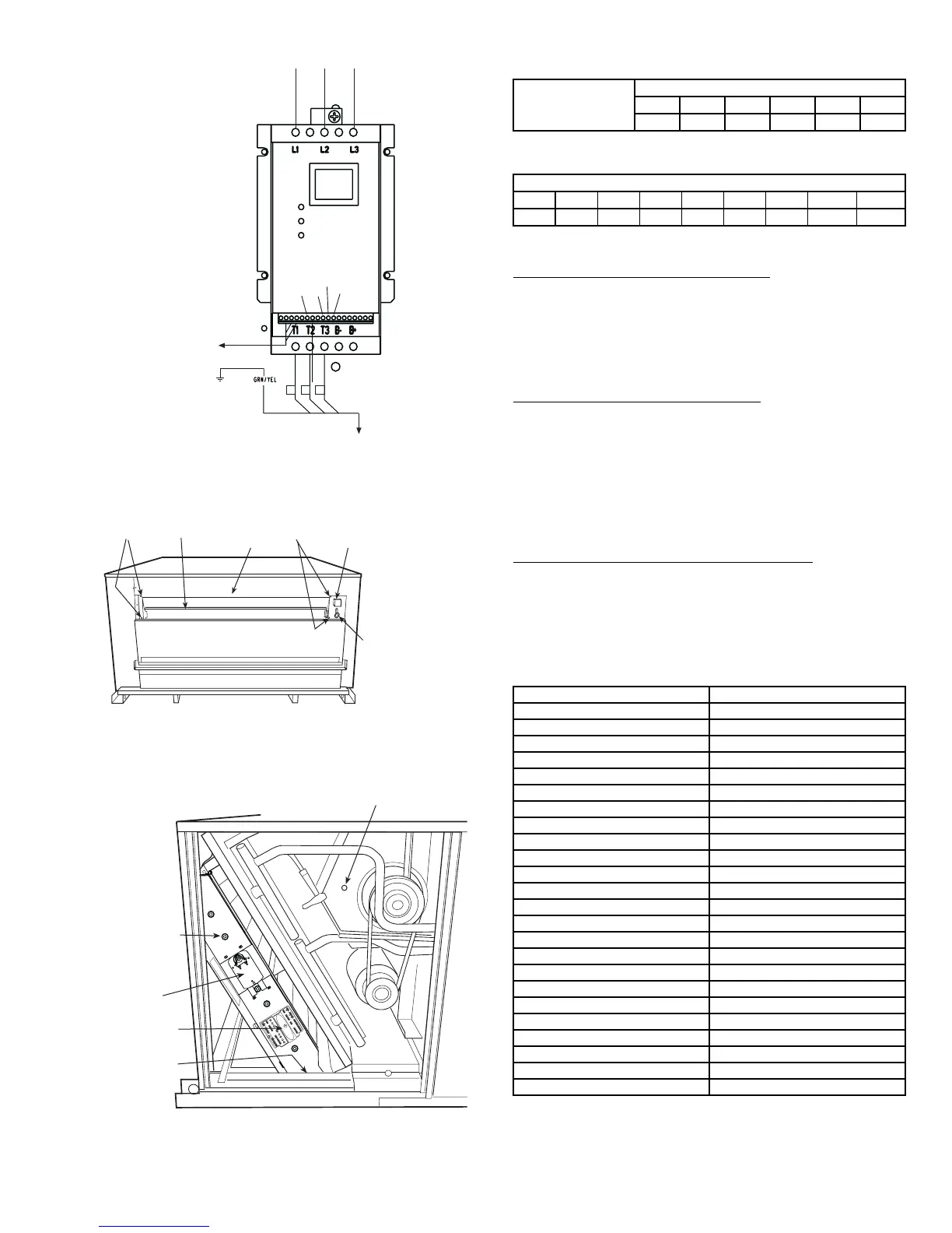
Fig. 23 — Motormaster® V Control
256
2
12 13A
13B
13C
1
2
3
TO MOTOR(S)
TO PRESSURE
TRANSDUCER
BLK
YEL
BLU
FROM FUSE BLOCK
B
Fig. 24 — EconoMi$erIV Component Locations —
End View
ECONOMI$ERIV
OUTDOOR AIR
TEMPERATURE SENSOR
(INSTALLED OPERATION
POSITION)
SCREWS
SCREWS
FRAME
TOP
LOW TEMPERATURE
COMPRESSOR
LOCKOUT SWITCH
Fig. 25 — EconoMi$erIV Assembled in Unit —
Side View
ACTUATOR
ECONOMI$ERIV
FLANGE
AND SCREWS
(HIDDEN)
CONTROLLER
SUPPLY AIR
TEMPERATURE SENSOR
LOCATION
T
R
1
2
4
V
a
c
C
O
M
T
R
2
4
V
a
c
H
O
T
1
2
3
4
5
E
F
E
F
1
+
_
P
1
T
1
P
T
N
E
X
H
2
V
1
0
V
E
X
H
S
e
t
S
e
t
2
V
1
0
V
2
V
1
0
V
D
C
V
D
C
V
F
r
e
e
C
o
o
l
B
C
A
D
S
O
+
S
R
+
S
R
S
O
A
Q
1
A
Q
D
C
V
M
i
n
P
o
s
O
p
e
n
M
a
x
N
1



 To Next Page