Service Manual
Table of contents
PAGE NO. PAGE NO.
UNIT IDENTIFICATION . . . . . . . . . . . . . . . . . . . . . . . . . . . . . . . . . 2
SAFETY CONSIDERATIONS . . . . . . . . . . . . . . . . . . . . . . . . . . . . . 2
General information . . . . . . . . . . . . . . . . . . . . . . . . . . . . . . . . . . . . . . 2
ELECTRICAL . . . . . . . . . . . . . . . . . . . . . . . . . . . . . . . . . . . . . . . . . . 3
Aluminum Wire . . . . . . . . . . . . . . . . . . . . . . . . . . . . . . . . . . . . . . . 3
ELECTRICAL SYSTEM OVERVIEW . . . . . . . . . . . . . . . . . . . . 3
Terminal Block . . . . . . . . . . . . . . . . . . . . . . . . . . . . . . . . . . . . . . 3
Transformer . . . . . . . . . . . . . . . . . . . . . . . . . . . . . . . . . . . . . . . . 3
Compressor / Fan Sub-System . . . . . . . . . . . . . . . . . . . . . . . . . . 3
Variable Frequency Drive (VFD) . . . . . . . . . . . . . . . . . . . . . . . . 5
VFD Filter Board . . . . . . . . . . . . . . . . . . . . . . . . . . . . . . . . . . . . 5
Reactors . . . . . . . . . . . . . . . . . . . . . . . . . . . . . . . . . . . . . . . . . . . 5
High Pressure Switch (HPS). . . . . . . . . . . . . . . . . . . . . . . . . . . . 5
Compressor Brushless Permanent Magnet Motor (BPM) . . . . . 5
VFD + Compressor BPM . . . . . . . . . . . . . . . . . . . . . . . . . . . . . . 5
Fan Brushless Permanent Magnet Motor (BPM) . . . . . . . . . . . . 5
VFD + Fan BPM. . . . . . . . . . . . . . . . . . . . . . . . . . . . . . . . . . . . . 5
Crankcase Heater . . . . . . . . . . . . . . . . . . . . . . . . . . . . . . . . . . . . 5
CONTROL SUB-SYSTEM. . . . . . . . . . . . . . . . . . . . . . . . . . . . . . 5
Primary Control Module (PCM). . . . . . . . . . . . . . . . . . . . . . . . . 5
Control Connection (Communicating and Non-Communicating). 5
Communicating Evolution Control. . . . . . . . . . . . . . . . . . . . . . . 5
Non-Communicating Control . . . . . . . . . . . . . . . . . . . . . . . . . . . 6
Table 1 – DIP Swtich Settings . . . . . . . . . . . . . . . . . . . . . . . . . . . . 6
PCM Indicators and Matrix Display . . . . . . . . . . . . . . . . . . . . . . 6
Model Plug . . . . . . . . . . . . . . . . . . . . . . . . . . . . . . . . . . . . . . . . . 8
Thermistors . . . . . . . . . . . . . . . . . . . . . . . . . . . . . . . . . . . . . . . . . 8
Pressure Sensors . . . . . . . . . . . . . . . . . . . . . . . . . . . . . . . . . . . . . 8
VFD Control Connection . . . . . . . . . . . . . . . . . . . . . . . . . . . . . . . . 8
Pressure Equalization Valve (PEV) . . . . . . . . . . . . . . . . . . . . . . 8
Reversing Valve (RVS) . . . . . . . . . . . . . . . . . . . . . . . . . . . . . . . 8
Heating Electronic Expansion Valve (EXV-H) . . . . . . . . . . . . . 8
Bluetooth® Module . . . . . . . . . . . . . . . . . . . . . . . . . . . . . . . . . . 8
Accessory Control Components. . . . . . . . . . . . . . . . . . . . . . . . . . . 8
Utility Curtailment . . . . . . . . . . . . . . . . . . . . . . . . . . . . . . . . . . . 8
Liquid Line Solenoid Valve (LLS) . . . . . . . . . . . . . . . . . . . . . . . 8
CONTROL FEATURES AND OPERATION . . . . . . . . . . . . . . . . . . 9
Equipment Configuration (Model Plug) . . . . . . . . . . . . . . . . . . . . 9
Performance Mode . . . . . . . . . . . . . . . . . . . . . . . . . . . . . . . . . . . . . 9
Compressor Operation . . . . . . . . . . . . . . . . . . . . . . . . . . . . . . . . . . 9
Compressor Protect Delay . . . . . . . . . . . . . . . . . . . . . . . . . . . . . 9
Starting . . . . . . . . . . . . . . . . . . . . . . . . . . . . . . . . . . . . . . . . . . . . 9
Running. . . . . . . . . . . . . . . . . . . . . . . . . . . . . . . . . . . . . . . . . . . . 9
Compressor Reliability Protection . . . . . . . . . . . . . . . . . . . . . . . 9
Sump Heat. . . . . . . . . . . . . . . . . . . . . . . . . . . . . . . . . . . . . . . . . . 9
Fan Operation . . . . . . . . . . . . . . . . . . . . . . . . .
. . . . . . . . . . . . . . 9
Intermittent Low Fan Speed . . . . . . . . . . . . . . . . . . . . . . . . . . . . 9
Fan Operating Exceptions. . . . . . . . . . . . . . . . . . . . . . . . . . . . . . 9
Cooling Control . . . . . . . . . . . . . . . . . . . . . . . . . . . . . . . . . . . . . 9
Heating Control. . . . . . . . . . . . . . . . . . . . . . . . . . . . . . . . . . . . . . 9
Super Heat Control . . . . . . . . . . . . . . . . . . . . . . . . . . . . . . . . . . . 9
Defrost Mode . . . . . . . . . . . . . . . . . . . . . . . . . . . . . . . . . . . . . . . . . 9
Defrost Interval. . . . . . . . . . . . . . . . . . . . . . . . . . . . . . . . . . . . . 10
Defrost Process . . . . . . . . . . . . . . . . . . . . . . . . . . . . . . . . . . . . . 10
PCM Indicators and Display Operation. . . . . . . . . . . . . . . . . . . . 10
Status Light. . . . . . . . . . . . . . . . . . . . . . . . . . . . . . . . . . . . . . . . 10
Comm Light . . . . . . . . . . . . . . . . . . . . . . . . . . . . . . . . . . . . . . . 10
VFD Comm Light. . . . . . . . . . . . . . . . . . . . . . . . . . . . . . . . . . . 10
Matrix Display . . . . . . . . . . . . . . . . . . . . . . . . . . . . . . . . . . . . . 10
Reprogrammability . . . . . . . . . . . . . . . . . . . . . . . . . . . . . . . . . . 10
TROUBLESHOOTING . . . . . . . . . . . . . . . . . . . . . . . . . . . . . . . . . . 11
TROUBLESHOOTING CONTROL FEATURES . . . . . . . . . . . 11
SYSTEM DIAGNOSTICS . . . . . . . . . . . . . . . . . . . . . . . . . . . . . 11
Table 2 – Model Plug Information. . . . . . . . . . . . . . . . . . . . . . . . 12
COMPONENT DIAGNOSTICS . . . . . . . . . . . . . . . . . . . . . . . . . 12
Table 3 – Variable Speed Compressor Resistances (ohm)
(winding resistance at 68°F /20°C) . . . . . . . . . . . . . . . . . . . . . . . 12
Table 4 – DC Voltage and PWM Measurement . . . . . . . . . . . . . 13
Table 5 – Thermistor Resistance (k-ohms) vs. Temperature. . . . 13
DIAGNOSTIC CODES AND TROUBLESHOOTING . . . . . . . 15
Table 6 – Fault Code Table . . . . . . . . . . . . . . . . . . . . . . . . . . . . . 25
REFRIGERATION SYSTEM . . . . . . . . . . . . . . . . . . . . . . . . . . . . . 34
Refrigerant . . . . . . . . . . . . . . . . . . . . . . . . . . . . . . . . . . . . . . . . . . 34
Compressor Oil . . . . . . . . . . . . . . . . . . . . . . . . . . . . . . . . . . . . . . 34
Servicing Systems on Roofs With Synthetic Materials. . . . . . . . 34
Synthetic Roof Precautionary Procedure . . . . . . . . . . . . . . . . . 34
Brazing. . . . . . . . . . . . . . . . . . . . . . . . . . . . . . . . . . . . . . . . . . . . . 34
Service Valves and Pumpdown . . . . . . . . . . . . . . . . . . . . . . . . . . 34
Pumpdown & Evacuation . . . . . . . . . . . . . . . . . . . . . . . . . . . . . 35
Pump Down . . . . . . . . . . . . . . . . . . . . . . . . . . . . . . . . . . . . . . . 35
Evacuation and Recovery of Refrigerant from 284ANV . . . . . 35
Reversing Valve (284ANV) . . . . . . . . . . . . . . . . . . . . . . . . . . . 35
Liquid Line Filter Drier . . . . . . . . . . . . . . . . . . . . . . . . . . . . . . . . 36
Install Liquid-line Filter Drier Indoor. . . . . . . . . . . . . . . . . . . . 36
Suction Line Filter Drier . . . . . . . . . . . . . . . . . . . . . . . . . . . . . . . 36
Thermostatic Expansion Valve (TXV) . . . . . . . . . . . . . . . . . . . . 36
TXV Operation . . . . . . . . . . . . . . . . . . . . . . . . . . . . . . . . . . . . . 37
Accumulator. . . . . . . . . . . . . . . . . . . . . . . . . . . . . . . . . . . . . . . . . 37
Vapor Injection Operation (5 Ton Models) . . . . . . . . . . . . . . . . . 37
Vapor Injection Electronic Exp. Valve (EXV VI)
(5 Ton Models) . . . . . . . . . . . . . . . . . . . . . . . . . . . . . . . . . . . . . . 38
REFRIGERATION SYSTEM REPAIR. . . . . . . . . . . . . . . . . . . . . . 38
Leak Detection . . . . . . . . . . . . . . . . . . . . . . . . . . . . . . . . . . . . . . . 38
Coil Removal . . . . . . . . . . . . . . . . . . . . . . . . . . . . . . . . . . . . . . . . 38
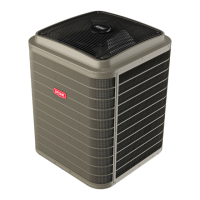
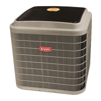
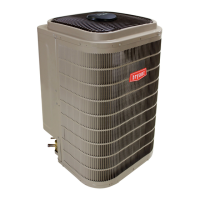
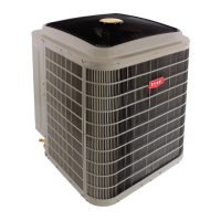
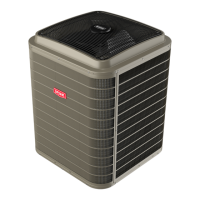
186CNV / 284ANV
Evolution™ Extreme
Variable Speed Air conditioner and Heat Pump
2 to 5 Nominal Tons






 Loading...