10
Table 2 – Maximum Gas Flow Capacity*
NOMINAL
IRON PIPE
SIZE (IN.)
INTERNAL
DIAMETER
(IN.)
LENGTH OF PIPE FT (m)†
10
(3)
20
(6)
30
(9)
40
(12)
50
(15)
60
(18)
70
(21)
80
(24)
90
(27)
100
(30)
125
(38)
150
(46)
175
(53)
200
(61)
1/2 .622
175
(53)
120
(37)
97
(30)
82
(25)
73
(22)
66
(20)
61
(19)
57
(17)
53
(16)
50
(15)
44
(13)
40
(12)
— —
3/4 .824
360
(110)
250
(76)
200
(61)
170
(52)
151
(46)
138
(42)
125
(38)
118
(36)
110
(34)
103
(31)
93
(28)
84
(26)
77
(23)
72
(22)
1 1.049
680
(207)
465
(142)
375
(114)
320
(98)
285
(87)
260
(79)
240
(73)
220
(67)
205
(62)
195
(59)
175
(53)
160
(49)
145
(44)
135
(41)
1 --- 1 / 4 1.380
1400
(427)
950
(290)
770
(235)
600
(183)
580
(177)
530
(162)
490
(149)
460
(140)
430
(131)
400
(122)
360
(110)
325
(99)
300
(91)
280
(85)
1 --- 1 / 2 1.610
2100
(640)
1460
(445)
1180
(360)
990
(302)
900
(274)
810
(247)
750
(229)
690
(210)
650
(198)
620
(189)
550
(168)
500
(152)
460
(140)
430
(131)
*Capacity of pipe in cu ft of gas per hr for gas pressure of 0.5 psig or less. Pressure drop of 0.5 ---in. wc (based on a 0.60 specific gravity gas). Refer to Table,
National Fire Protection Association NFPA 54.
{ This length includes an ordinary number of fittings.
1. Open all electrical disconnects before starting any service
work.
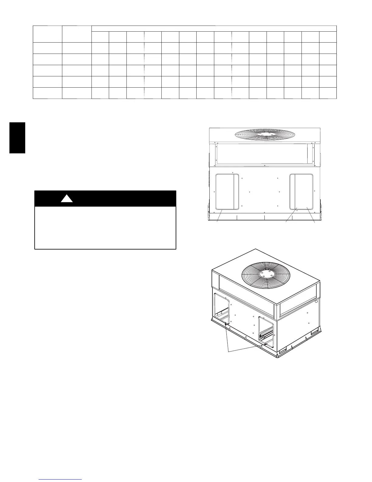
2. Remove horizontal (metal) duct covers to access vertical
(downflow) discharge duct knockouts in unit base.
3. Use a screwdriver and hammer to remove the panels in the
bottom of the unit base (See Fig. 10).
4. If unit ductwork is to be attached to vertical opening flanges
on the unit base (jackstand applications only), do so at this
time.
PROPERTY DAMAGE HAZARD
Failure to follow this caution may result in property
damage.
Collect ALL screws that were removed. Do not leave
screws on rooftop as permanent damage to the roof may
occur .
CAUTION
!
5. It is recommended that the base insulation around the
perimeter of the vertical return--air opening be secured to
the base with aluminum tape. Applicable local codes may
require aluminum tape to prevent exposed fiberglass.
6. Cover both horizontal duct openings with the provided duct
covers. Ensure opening is air-- and watertight.
7. After completing unit conversion, perform all safety checks
and power up unit.
NOTE: The design and installation of the duct system must be in
accordance with the standards of the NFP A for installation of
nonresidence-- type air conditioning and ventilating systems, NFPA
90A or residence--type, NFPA 90B; and/or local codes and
ordinances.
SUPPLY
DUCT
OPENING
RETURN
DUCT
OPENING
VENT HOOD
SHIPPING
LOCATION
A05143
Fig. 9 -- Supply and Return Duct Opening
DUCT COVERS REMOVED
C99012
Fig. 10 -- Vertical Duct Cover Removed
Adhere to the following criteria when selecting, sizing, and
installing the duct system:
1. Units are shipped for horizontal duct installation (by
removing duct covers).
2. Select and size ductwork, supply--air registers, and
return--air grilles according to American Society of Heating,
Refrigeration and Air Conditioning Engineers (ASHRAE)
recommendations.
3. Use flexible transition between rigid ductwork and unit to
prevent transmission of vibration. The transition may be
577C
 Loading...