12
Control Voltage Connections
Do not use any type of power-- stealing thermostat. Unit control
problems may result.
Use no. 18 American Wire Gage (AWG) color--coded, insulated
(35_C minimum) wires to make the control voltage connections
between the thermostat and the unit. If the thermostat is located
more than 100 ft (30.5 m) from the unit (as measured along the
control voltage wires), use no. 16 AWG color-- coded, insulated
(35_C minimum) wires.
Standard Connection
Remove knockout hole located in the flue panel adjacent to the
control access panel (See Fig. 3 and 4). Remove the rubber
grommet from the installer’s packet (included with unit) and install
grommet in the knockout opening. Provide a drip loop before
running wire through panel.
POWER
SUPPLY
FIELD-SUPPLIED
FUSED DISCONNECT
HIGH VOLTAGE
POWER LEADS
(SEE UNIT WIRING
LABEL)
GR
CONTROL BOX
SPLICE BOX
LOW-VOLTAGE
POWER LEADS
(SEE UNIT
WIRING LABEL)
W
Y
G
R
C
WHT(W1)
YEL(Y)
GRN(G)
RED(R)
BRN(C)
THERMOSTA
(TYPICAL)
A05144
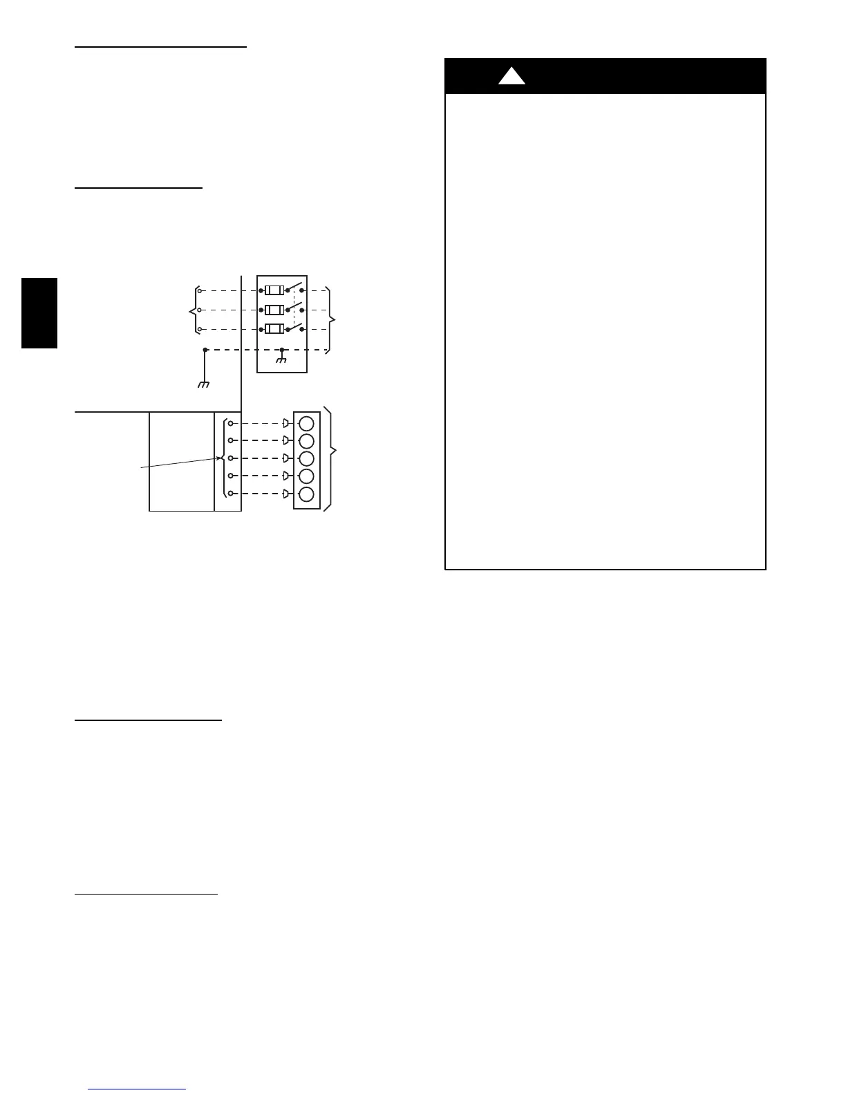
Fig. 11 -- High-- and Control--Voltage Connections
Run the low-- voltage leads from the thermostat, through the inlet
hole, and into unit low--voltage splice box.
Locate five 18-- gage wires leaving control box. These low--voltage
connection leads can be identified by the colors red, green, yellow ,
brown, and white (See Fig. 11). Ensure the leads are long enough
to be routed into the low-- voltage splice box (located below right
side of control box). Route leads through hole in bottom of control
box and make low--voltage connections (See Fig. 11). Secure all
cut wires, so that they do not interfere with operation of unit.
Heat Anticipator Setting
The room thermostat heat anticipator must be properly adjusted to
ensure proper heating performance. Set the heat anticipator, using
an ammeter between the W and R terminals to determine the exact
required setting.
NOTE: For thermostat selection purposes, use 0.18 amp for the
approximate required setting. Failure to make a proper heat
anticipator adjustment will result in improper operation, discomfort
to the occupants of the conditioned space, and inefficient energy
utilization; however, the required setting may be changed slightly
to provide a greater degree of comfort for a particular installation.
Transformer Protection
The transformer is of the energy--limiting type. It is set to withstand
a 30 -- sec. overload or shorted secondary condition. If an overload
or short is present, correct overload condition and check for blown
fuse on gas control board. Replace fuse as required with correct
size and rating.
PRE--START -- UP
ENVIRONMENTAL, FIRE, EXPLOSION,
ELECTRICAL SHOCK HAZARD
Failure to follow this warning could result in personal
injury or death.
1. Follow recognized safety practices and wear protective
goggles when checking or servicing refrigerant system.
2. Do not operate compressor or provide any electric power
to unit unless compressor terminal cover is in place and
secured.
3. Do not remove compressor terminal cover until all
electrical sources are disconnected and tagged.
4. Relieve and recover all refrigerant from system before
touching or disturbing anything inside terminal box if
refrigerant leak is suspected around compressor
terminals.
5. Never attempt to repair soldered connection while
refrigerant system is under pressure.
6. Do not use torch to remove any component. System
contains oil and refrigerant under pressure.
To remove a component, wear protective goggles and
proceed as follows:
a. Shut off electrical power to unit and install
lockout tag.
b. Relieve and reclaim all refrigerant from system
using both high-- and low--pressure ports.
c. Cut component connecting tubing with tubing
cutter and remove component from unit.
d. Carefully unsweat remaining tubing stubs when
necessary. Oil can ignite when exposed to torch
flame.
!
WARNING
Use the Start--Up Checklist supplied at the end of this book and
proceed as follows to inspect and prepare the unit for initial
start--up:
1. Remove access panel.
2. Read and follow instructions on all DANGER, WARNING,
CAUTION, and INFORMATION labels attached to, or
shipped with unit.
3. Make the following inspections:
a. Inspect for shipping and handling damage, such as
broken lines, loose parts, disconnected wires, etc.
b. Inspect for oil at all refrigerant tubing connections and
on unit base. Detecting oil generally indicates a
refrigerant leak.
c. Leak --test all refrigerant tubing connections using
electronic leak detector, or liquid-- soap solution. If a
refrigerant leak is detected, see following Check for
Refrigerant Leaks section.
d. Inspect all field-- and factory--wiring connections. Be
sure that connections are completed and tight.
e. Ensure wires do not touch refrigerant tubing or sharp
sheet metal edges.
f. Inspect coil fins. If damaged during shipping and
handling, carefully straighten fins with a fin comb.
577C
 Loading...