10
STANDARD CONNECTION
Locate the seven (eight for 3 --phase) low voltage thermostat leads
in 24 volt splice box. A gray wire is standard on 3 --phase units for
connection to an economizer. See Fig. 10 for connection diagram.
Run the low --voltage leads from the thermostat, through the control
wiring inlet hole grommet (Fig. 2 and 3), and into the low--voltage
splice box. Provide a drip loop before running wires through panel.
Secure and strain relief all wires so that they do not interfere with
operation of unit.
If an accessory electric heater is installed, low voltage leads from
heater must be connected to factory supplied control leads from
Indoor Fan Board P4 connector. Factory wires are provided for
electric heat staging W1 and W2 (W2 and W3 on IFB). If room
thermostat has only one stage of supplemental heat, connect white
and violet wires shown in Fig. 10 to second stage heat field wire.
Some electric heaters have four control wires (plus common wire).
Consult unit wiring diagram and electric heater wiring diagram for
additional details.
TRANSFORMER PROTECTION
The transformer is of the energy--limiting type, however a direct
short will likely blow a secondary fuse. If an overload or short is
present, correct overload condition and check for blower fuse on
Indoor Fan Board. Replace fuse as required with correct size and
rating.
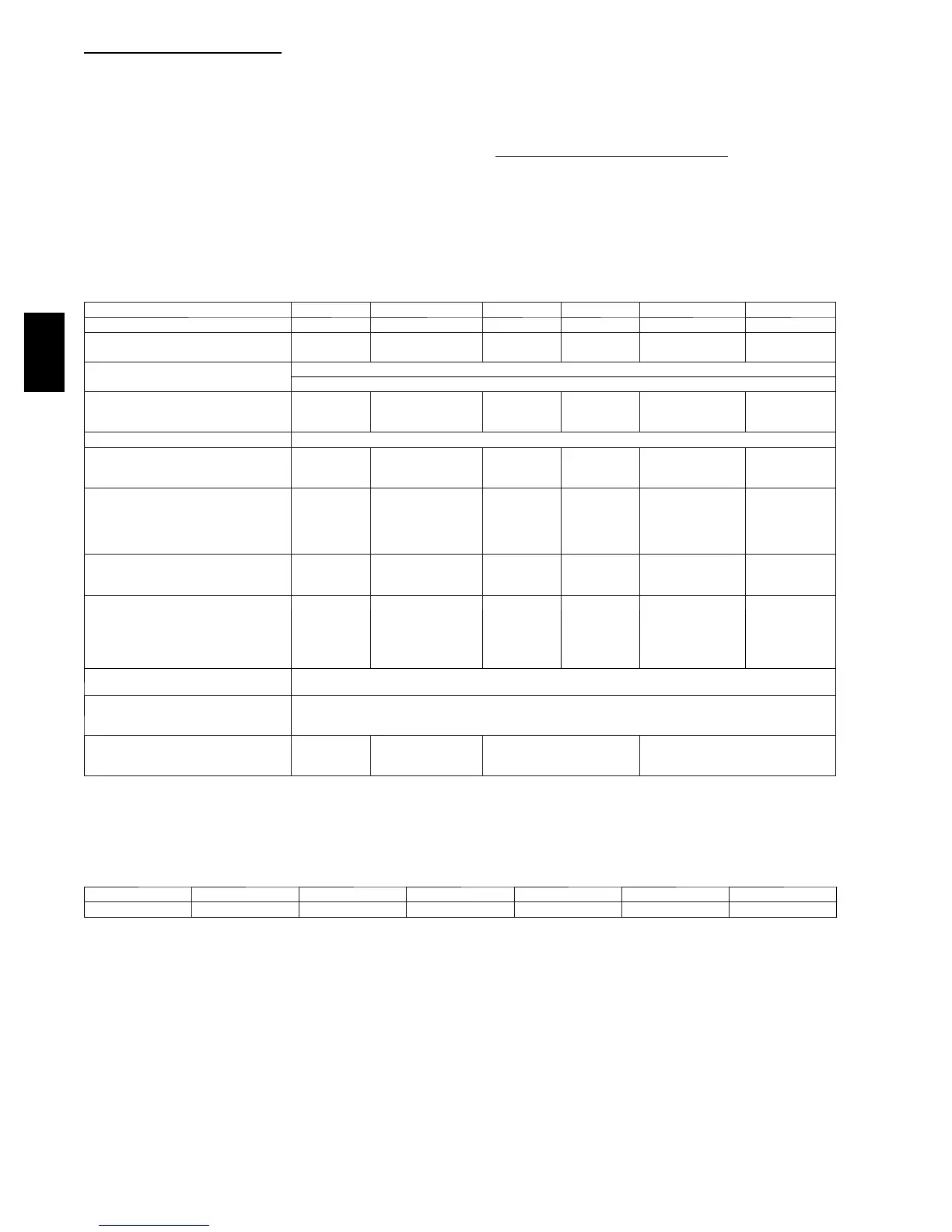
Table 1 – Physica l Data--Unit 704D ----A
UNIT SIZE 24 30 36 42 48 60
NOMINAL CAP ACITY (ton) 2 2 --- 1 / 2 3 3 --- 1 / 2 4 5
SHIPPING WEIGHT* lb.
SHIPPING WEIGHT* (kg)
279
127
284
129
290
132
378
171
384
174
406
184
COMPRESSORS
Quantity
Scroll
1
REFRIGERANT (R --- 410A)
Quantity lb
Quantity (kg)
4.8
2.2
6.2
2.8
6.4
2.9
6.1
2.7
6.4
2.9
10.0
4.5
REFRIGERANT METERING DEVICE TXV
OUTDOOR COIL
Rows...Fins/in.
Face Area (sq ft)
1...21
10.2
1...21
11.9
1...21
15.4
1...21
13.6
1...21
15.5
2...21
15.5
OUTDOOR FAN
Nominal Cf m
Diameter in.
Diameter (mm)
Motor Hp (Rpm)
2800
24
610
1/5 (810)
3000
24
610
1/5 (810)
3200
24
610
1/5 (810)
3600
26
660
1/5 (810)
4000
26
660
1/5 (810)
3200
26
660
1/5 (810)
INDOOR COIL
Rows...Fins/in.
Face Area (sq ft)
2...17
3.7
3...17
3.7
3...17
3.7
3...17
4.7
3...17
4.7
3...17
5.7
INDOOR BLOWER
Nominal Cooling Airflow (Cfm)
Size in.
Size (mm.)
Motor HP (RPM)
800
10x10
254x254
1/2 (1050)
1000
10x10
254x254
1/2 (1050)
1200
11x10
279.4x254
3/4 (1000)
1400
11x10
279.4x254
3/4 (1075)
1600 1750
11x10
279.4x254
11x10
279.4x254
1.0 (1075) 1.0 (1040)
HIGH --- PRESSURE SWITCH
(psig) Cut---out Reset (Auto)
650 +/--- 15
420 +/--- 25
L O S S --- O F --- C H A R G E / L O W --- P R E S -
SURE SWITCH (Liquid Line) (psig)
cut---out Reset (auto)
2 0 + / --- 5
45 +/--- 10
RETURN ---AIR FILTERS†}
Throwaway Size in.
Throwaway Size (mm)
20x20x1
508x508x25
20x24x1
508x610x25
24x30x1
610x762x25
24x36x1
610x914x25
*For 460 volt units add 14 lb (6.35 kg) to the shipping weight.
{ Required filter sizes shown are based on the larger of the AHRI (Air Conditioning, Heating and Refrigeration Institute) rated cooling airflow or the heating
airflow velocity of 300 ft/minute for throwaway type or 450 ft/minute for high---capacity type. Air filter pressure drop for non ---standard filters must not exceed 0.08
IN. W.C.
} If using accessory filter rack refer to the filter rack installation instructions
for correct filter sizes and quantity.
Table 2 – Minimum Airflow for Safe Electric Heater Operation (CFM)
SIZE 24 30 36 42 48 60
Cfm 800 1000 1200 1400 1600 1750
704D-- -- A

 Loading...