Cut the boat tail jig into two pieces, again using a knife. Tape the pieces back together. Eventually, the rear
piece will be glued permanently into the structure, and the front piece will be removed.
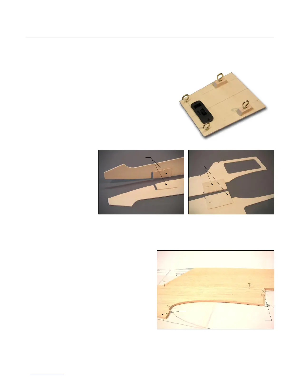
Prepare your lite-ply receiver shelf to suit your planned radio
installation, which may differ from what is shown here. I like to put
the cup hooks in place now, because clearance inside the fuselage
can be an issue if you wait until later. The front end of the shelf is a
handy place for the receiver switch, but it's up to you.
Glue the D-1 receiver shelf positioners to the lite-ply doublers.
CAUTION! Be sure to make a right-hand and a left-hand fuselage
doubler. It is critical to align the positioners with their bottom edges
flush with the bottom edge of the doubler.
Do the same for the D-2 ECU shelf positioner, but be careful!
D-2 is not a rectangle. Use
the plan to mark the bottom
edge and add an arrow
pointing forward on each D-2
to aid in positioning.
The fuselage plans are
printed in two pieces. Cut one
(or both) accurately along the
join line, then tape the two
pieces together. Use a long
straightedge to check some of the straight horizontal lines to be sure the plan sheets are aligned properly.
Build the two 1/4" balsa fuselage sides over the plans (protected with wax paper). Start by pinning down SIDE-1.
You may see slight discrepancies with the plan, but I suggest making sure it is positioned accurately along its rear
edge and the wing saddle. Add SIDE-2 through SIDE-5,
in that order, using yellow glue or thick CA.
Lay the fuselage side back on the plan and draw the
positions of the F-7 and F-8 bulkheads on the INSIDE of
each fuselage side. NOTE: The notches on the SIDE-1
pieces will go on the OUTSIDE surface of the fuselage.
You should now have one left-hand and one right-hand
fuselage side assembly.
R54
SIDE-1
SIDE-2 Don't worry if
it's oversize - it will be
trimmed later
SIDE-3
Watch
the Notch
D-1
D-2
FUSELAGE SUBASSEMBLIES, continued...
17
Receiver
Shelf


 To Next Page