4
03/10/2016BT00680-c-
346310
N°
AUX
MOD
T - C + -
230 Vac
1- 2
2 1
ON
346851
ON
OFF
ON
346851
ON
OF F
BUS 2 1
SC S
OUT1 OUT2 OUT3 OUT 4
IN1IN2
IN3
IN4
OUT
IN
230V a.c .
OFFON OFFONOFFON
ON
346851
ON
OFF
BUS
OUT
I N
C
F422
230V a.c .
M
= –
= 1
MOD
= 5
M
= –
= 3
MOD
= 5
M
= –
= 2
MOD
= 5
N° = 2
AUX = 1-9
MOD = –
Z1 = 9
N1 = 1
MOD1 = –
Z2 = –
N2 = –
MOD2 = 1-9
I1 = –
I2 = –
I3 = –
I4 = 1
MOD = 3
346310
346851
346851 346851
F441
346000
346020
F422
E46ADCN
3480
4615
EN
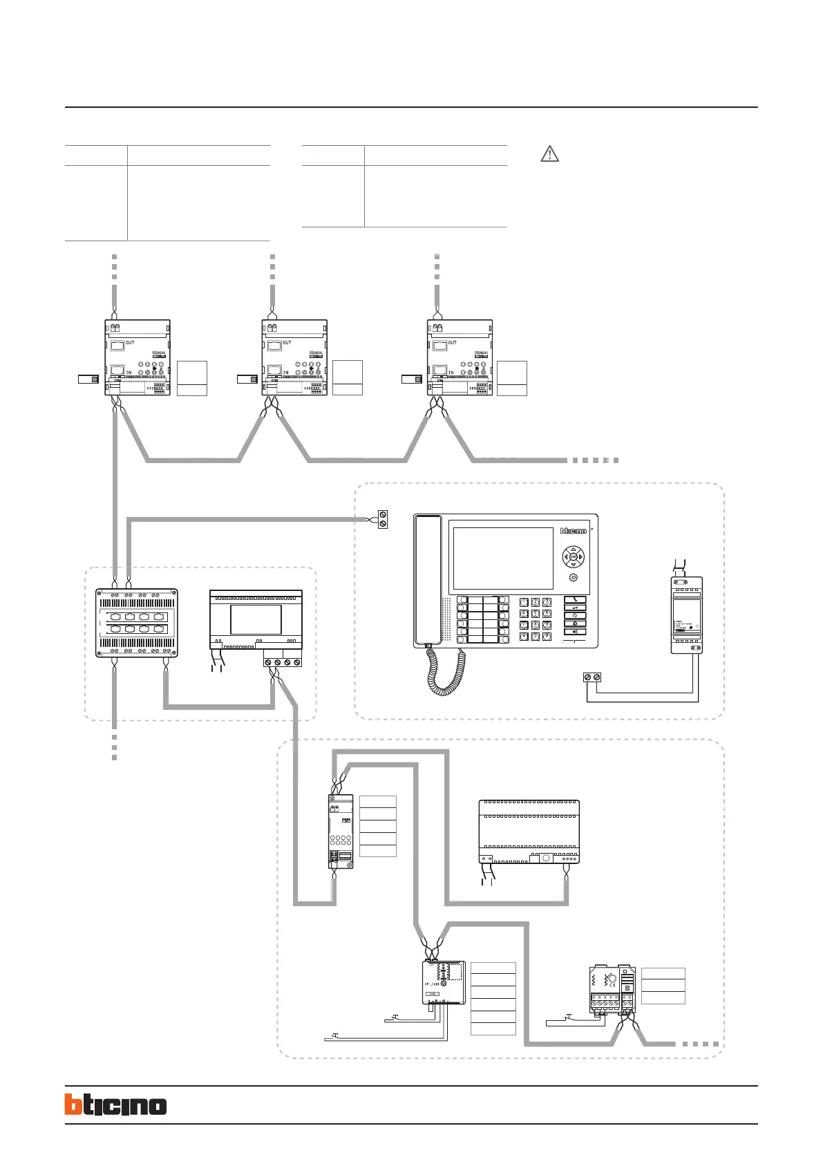
2 WIRE Switchboard
System with a switchboard independent risers and possible alarm display from common parts in backbone
ITEM DESCRIPTION
346310 Switchboard
346020 Additional power supply
F441 Audio/video node
346000 Power supply
E46ADCN Power supply
ITEM DESCRIPTION
F422 SCS/SCS gateway
3480 Contact interface
4615 Auxiliary channel interface
346851 System expansion module
– An additional power supply with 346020 is recommended
– FUse the YouDiagram software for the functional check and
calculation of the current absorptions – free download from
the website:
www.professionisti.bticino.it (for Italy)
www.bticino.com (International version).
– For the configuration of the switchboard refer to the
documentation supplied with the product or the
configuration software
– Using interface item F422O it is possible to connect the
contact interfaces for the management of alarms on the
common parts (max. 9 interfaces) - e.g. door/window
contacts and technical alarms (gas, water, etc.). Refer to the
specific MyHOME documentation
– All apartment and common alarms are only managed by the
main switchboard (configured with 0)
WARNING
Master SWB = 0
Riser 1 Riser 3Riser 2
To other interfaces 346851
Main EP
(P = 1)
OPTIONAL ONLY FOR ALARM MANAGEMENT
NC pushbutton
NC
pushbutton
Technical alarm activation
NO pushbutton
Alarm Reset

 Loading...