EasyManua.ls Logo

Bticino D45 User Manual

Bticino D45
6 pages
To Next Page IconTo Next Page
Page #1 background imageLoading...
Page #1 background image
1
322010
325 mm
125 mm 62,7 mm
23 mm
1
11
10
9
8
7 2
3
6 45
D45 System
Description
Digital colour entrance panel
D45 System entrance panel with colour camera and backlighted alphanumeric
keyboard equipped with : pushbutton to direct calls to the porter switchboard; door
lock opening with a numeric code to residents. Possibility to send an alarm message
to the switchboard when opening over 2 minutes of the associated lock or when trying
to remove the device. Setup key functions via keyboard, programming and heading
residents through the dedicated software supplied with the product. Flush mounting
installation with dedicated box - supplied with the product.
Technical data
Power supply: 30 Vdc
Stand by absorption: ≤ 110 mA @ 30 V
Max operating absorption: ≤ 290 mA@30 V
Camera diagonal view angle: 90°
Camera distance up to clear picture: 40 – 50 cm
Camera resolution: 537 x 597
Camera minimum lux level visibility: 0.5 Lux
Operating temperature: (-25) – (+55) °C
Protection index: IP54
Protection against mechanical impact: IK07
Dimensional data
Legend
1. Compensation Lamp
2. Confirm menu setting or other operation pushbutton
3. Numerical keyboard: internal unit call & function setting
4. Switchboard call pushbutton
5. Microphone
6. Photosensitive lamp
7. Return or quit menu setting pushbutton
8. Alphanumerical pushbuttons
9. LCD Display
10. Loudspeaker
11. Colour camera
Front view
BT00466-b-EN 30/05/2013

Other manuals for Bticino D45

Question and Answer IconNeed help?

Do you have a question about the Bticino D45 and is the answer not in the manual?

Bticino D45 Specifications

General IconGeneral
CameraYes
TypeVideo Intercom
MountingSurface
Wiring2-wire
Night VisionYes
CompatibilityBticino systems

Summary

Product Description

Description

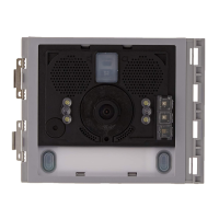
Overview of the D45 System entrance panel with colour camera and alphanumeric keyboard functionality.

Technical Data

Dimensional Data

Front View Components

Legend

Identification of numbered components visible on the front view of the entrance panel.

Rear View and Configuration

Configuration Parameters

Explanation of parameters NN, #FF, and #II for system configuration.

Configuration Modes

Details on two different configuration modes (MODE 1 and MODE 2) for the system.

Mode 1 Example

Example scenario for system configuration using MODE 1.

Mode 2 Example

Example scenario for system configuration using MODE 2.

Device Keyboard Configuration (WAY 1)

Master Password Setting

Procedure for changing the master password via the device keyboard.

Signal Type Setting

Setting signal types for electric door locks (often-closed/often-opened).

Anti-Removal Alarm Setting

Configuration and activation of the anti-removal alarm function.

Room Number Mode Setting

Setting room number configurations, including Riser and Backbone modes.

Device Keyboard Configuration (WAY 1 - Continued)

Entrance Panel Configuration Parameters

Setting entrance panel address, floor, and maximum handsets per floor.

Language Setup

Procedure for selecting the system language.

Unlock Pulse Width Setting

Setting the duration for the door lock release pulse.

Door Lock Release Password Function

Enabling/disabling and managing door lock release passwords.

Physical Configurator Settings (WAY 2)

Physical Connection

Instructions for connecting physical configurators to the device.

Configurator Value Definitions

Explanation of configurator positions (N, #F, #II) and their values.

Configuration Examples

Illustrative examples of system configuration using physical configurators.

Software Configuration (WAY 3)

SF2 Software and PC Connection

Downloading device configuration using SF2 software and a PC.

Video Gain Setting

Adjusting video signal output based on transmission distance using V-GAIN gears.

Door Lock Relay Connection

Wiring diagram for connecting the door lock relay.

Related product manuals