2
323018
CF1 CF2 CF3 CF4 CF5 CF6
MC
min
MC
min
MC
max
MC
mac
DEV DIR
CF1 CF2 CF3 CF4 CF5 CF6
MC
min
MC
min
MC
max
MC
mac
DEV DIR
1 2 3 4 5 6
CF1 CF2 CF3 CF4 CF5 CF6
MIN MIN MAX MAX DEV DIR
0 4 0 4 0 1
CF1 CF2 CF3 CF4 CF5 CF6
MIN MIN MAX MAX DEV DIR
0 4 0 5 1 0
CF1 CF2 CF3 CF4 CF5 CF6
MIN MIN MAX MAX DEV DIR
0 4 0 5 1 1
Entrance panel/Switchboard shunt
Configuration
Two different device configuration ways available:
WAY 1) Configuration settings by inserting phisical configurators
WAY 2) Configuration by using SF2 Software and PC connection
Configuration by inserting phisical configurators - WAY 1:
Meaning of the configuration places:
*Min: the minimal number connected to the Backbone/main EP or to the switchboard
at main EP/Switchboard of interface.
**Max: the maximal number connected to the Backbone/main EP or to the switchboard
at main EP/Switchboard of interface.
CONFIGURATION PLACE MODE 1 MODE 2
CF1
Min*
Same as Mode 1
CF2
CF3
Max**
CF4
CF5 DEV
CF6 DIR
DEV = options of main EP/Switchboard types:
DEV
0 Switchboard
1 Backbone/main EP
DIR: options of main EP/Switchboard wiring directions:
DIR
0 The Switchboard is connected to the B1 interface and backbone/main EP to the B2 interface
1 The backbone/main EP is connected to B1 and the Switchboard to B2
The DIR configuration for the device wiring direction must satisfy the following rules or
they will lead to irregular working of the system :
1. Riser shunt must be connected at the B1 connector interface of all interface in the
relevant zone.
2. The wiring direction of the switchboard and the main EP can be set through the
DIR configuration place, but all of interfaces wiring directions must be identically
configured in the project.
3. Pushbutton-configuration operation (it will be invalid when the configurator is
inserted).
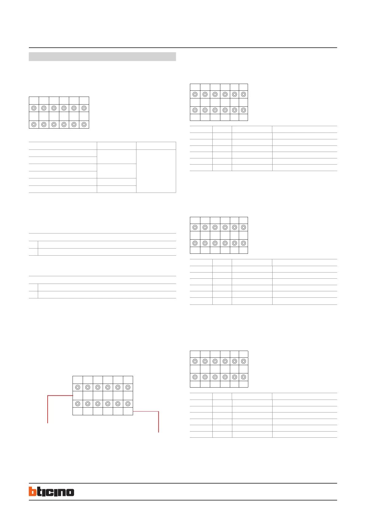
Value of the configuration place (from 0 – 9)
Code of the configuration place (1 to 6)
Configuration examples:
Example (A):
Item 323018 is used to extend one switchboard. The switchboard address range is 4; all
main EP are installed in the B1 port of 323018, configuration as follows:
Configuration examples:
Example (C):
Item 323018 is used to extend one Switchboard, Switchboard address range is 4; all
main EP are installed in the B1 port of 323018, configuration as follows:
POSITION MODE 1 VALUE FOR CONFIG. REMARKS
CF1 MIN 0 x
CF2 MIN 4 x
CF3 MAX 0 x
CF4 MAX 4 x
CF5 DEV 0 x
CF6 DIR 1 x
Configuration examples:
Example (B):
Item 323018 used to extend the main EP. The main EP address range is 4 to 5; all switch-
boards are installed in the B1 port of 323018, configuration as follows:
POSITION MODE 1 VALUE FOR CONFIG. REMARKS
CF1 MIN 0 x
CF2 MIN 4 x
CF3 MAX 0 x
CF4 MAX 5 x
CF5 DEV 1 x
CF6
DIR 0
x
POSITION MODE 1 VALUE FOR CONFIG. REMARKS
CF1 MIN 0 x
CF2 MIN 4 x
CF3 MAX 0 x
CF4 MAX 5 x
CF5 DEV 1 x
CF6 DIR 1 x
BT00463-b-EN 13/05/2013

 Loading...