GENERAL RULES FOR INSTALLATION
Max. distances and cable features
When sizing the system remember the following system limits as a function
of the type of amplifi er installed and the impedance features of the
loudspeaker used.
To keep the fi delity of the audio signal reproduced unaltered, lay the wiring
of the BUS 2 wire Sound /Video door entry System and the accessory wirings
(cables for loudspeakers etc.) in separate piping from the power cables
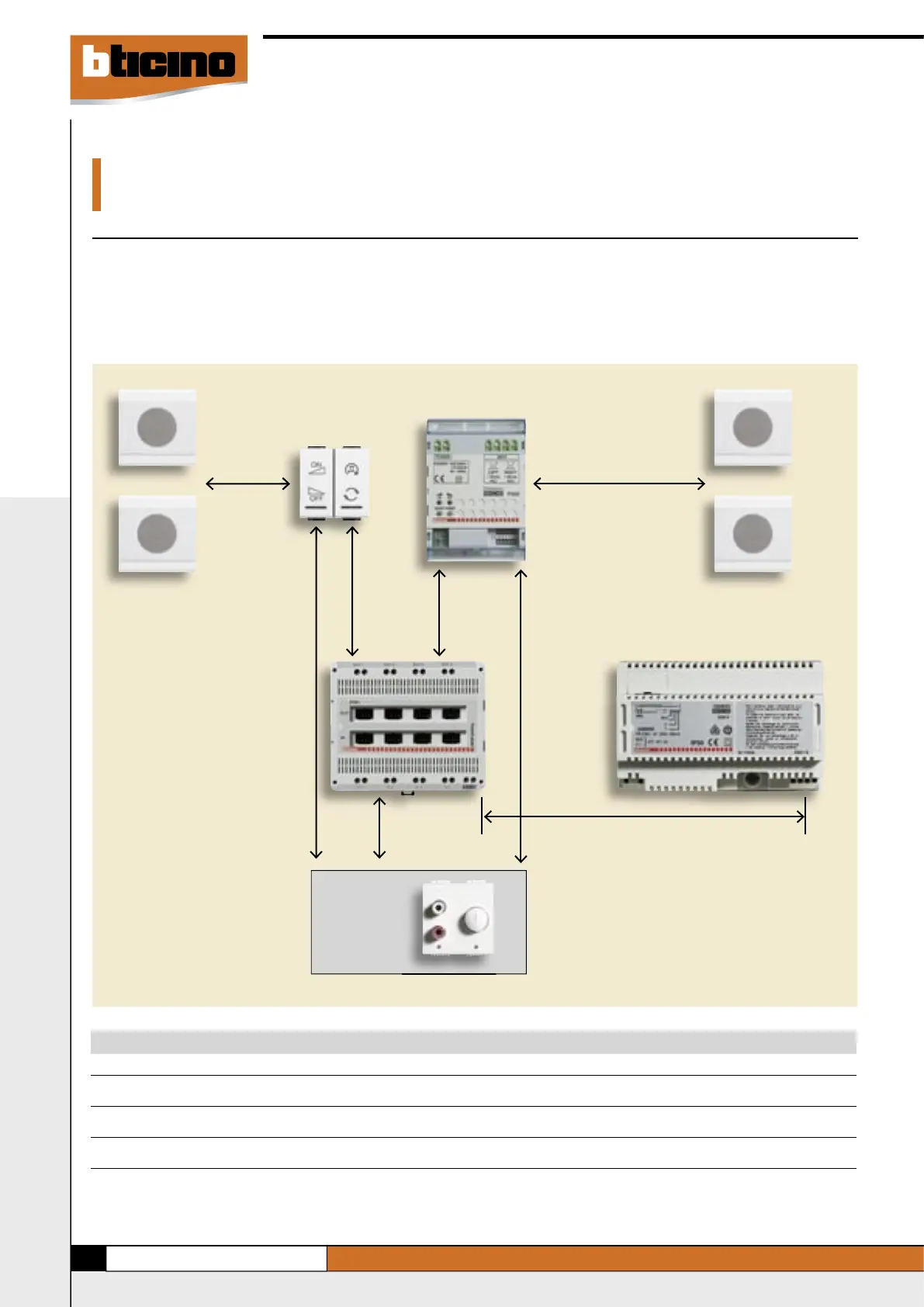
Generic audio
source
max. 10m
Loudspeakers
Audio/
video
node
A
Max. distance between the devices (A)
Maximum cable length on the basis of the number of amplifi ers item L4562 installed along an output of the audio/video Node
Loudspeaker impedance With No. 1 With No. 2 With No. 3 With No. 4
amplifi er amplifi ers amplifi ers amplifi ers
Using cable Item 336904 8o 160m 60m - -
16o 200m 160m 100m 60m
Using cable UTP cat.5E 8o 80m 30m - -
16o 160m 80m 50m 30m
NOTE: - using amplifi ers DIN item F502, a maximum of 10 amplifi ers can be cabled for each audio/video node output
- for the lengths of the Video door entry wirings, refer to the Technical Communication Guide
- total stretched cable max 800m.
- max. 30m with cable 1.5 mm
2
- max. 15m with cable 0.5 mm
2
max. 300m
max. 200m
max. 200m
Loudspeakers
max. 5m
max. 300m
Power supply
(230V line). The above wirings can only share inside junction boxes using
cables with suitable insulation (e.g. Item 336904).
Failure to respect the above provisions may affect the quality of the audio
signal reproduced.
 Loading...