EasyManua.ls Logo

Buchi Vac V-511 - User Manual

Buchi Vac V-511
28 pages
Print Icon
To Next Page IconTo Next Page
Loading...
1
BÜCHI Vac V-511/512/513 Table of Contents
Table of Contents
en, Version E (28 pages) Order No.
V-511 Operating Instructions 96716
1 Supplied Materials 2
1.1 Büchi Vac V-511 2
1.2 Büchi Vac V-512 3
1.3 Büchi Vac V-513 4
2 Safety 5
3 Function 8
3.1 General 8
4 Beginning Operation 10
4.1 General 10
4.2 Installation 11
5 Operation 14
5.1 Vacuum Systems 14
5.2 Troubleshooting 16
6 Maintenance 17
6.1 Cleaning 17
6.2 Removal and Assembly of the Pump Heads,
Valve Heads and Diaphragms 18
6.3 Function control 21
6.4 Customer Service 22
6.5 Working with strong acids / bases on
Büchi VAC V-500 – 513 22
7 Shutting Down 23
8 Spare Parts and Accessories 24
8.1 Spare parts 24
8.2 Accessories 25
9 Appendix 26
9.1 Technical data 26
9.2 Materials used 27
9.3 FCC requirements (for USA and Canada) 28
9.4 Declaration of confirmity 28
Please read these operating instructions
carefully before using the BÜCHI Vac V-511/
512/513. Keep these instructions in the
proximity of the apparatus so that you can
consult them immediately whenever
necessary.
Chapter 2 contains important safety instruc-
tions. Read them carefully; they are essential
for the safe operation of the apparatus.
Technical changes may be made without prior notice. These
operating instructions may not, either wholly or in part, be re-
produced or rewritten by the use of electronic or optical sys-
tems, copied, or distributed without the express written per-
mission of the firm BÜCHI Labortechnik AG. All rights reserved.
Copyright © BÜCHI Labortechnik AG 1998, 2000, 2001
Question and Answer IconNeed help?

Do you have a question about the Buchi Vac V-511 and is the answer not in the manual?

Overview

The BÜCHI Vac V-511/512/513 is a laboratory vacuum apparatus designed for various applications requiring controlled vacuum. It is built with state-of-the-art technology and adheres to recognized safety regulations.

Function Description

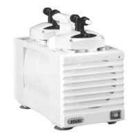
The BÜCHI Vac V-511/512/513 series consists of PTFE diaphragm pumps, with or without an integrated Vacuum Controller V-800, and an integrated additional condenser.

The V-511 system operates in continuous mode once the main switch is turned on, without the Vacuum Controller V-800. It includes a PTFE diaphragm pump and an integrated additional condenser.

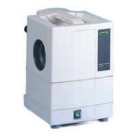
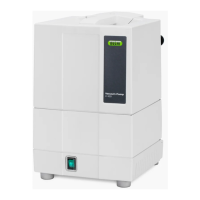
The V-512 and V-513 systems feature an integrated Vacuum Controller V-800, which creates and regulates a vacuum, maintaining it at a constant level. This is achieved by automatically compensating for any vacuum loss in the evacuated device and returning to the selected set pressure by directly turning the integrated PTFE diaphragm pump on and off.

The vacuum level can be selected according to the solvent being used, allowing for almost 100% condensation in the distillation apparatus's condenser, significantly reducing solvent emissions. The integrated additional condenser ensures that any suctioned solvent vapors are condensed to their physical limit after the pump.

Cooling water control is also possible during distillation, optionally handled by a cooling water valve, which can save up to 95% of water.

Additional functions include:

  • Automatic performance of distillations until dry, if physically possible without solvent loss (redistillation).
  • Automatic continued distillation until completion of a manually started distillation (ee.g., with problematic solvent mixtures).

Important Technical Specifications

  • Device Measurements (width x depth x height): 230 x 470 x 393 mm
  • Weight: 14-17 kg
  • Voltage:
    • 220 VAC 60 Hz, +/-10%
    • 230 VAC 50 Hz, +/-10%
    • 120 VAC 50/60 Hz, +/-10%
    • 100 VAC 50/60 Hz, +/-10%
  • Electrical Supply:
    • V-511: 240 W
    • V-512: 260 W
    • V-513: 260 W
  • Installation Category: II
  • Pollution Degree: 2
  • Ambient Conditions: For indoor use only, altitude up to 2000 m. Maximum relative humidity 80% for temperatures up to 30°C.
  • Support: T400mAL 250V
  • Surrounding Temperature: 5 - 40° C
  • Relative Humidity: max. 80%
  • Degree of Contamination: 2
  • Final Vacuum Possible: < 10 mbar
  • Pumping Volume: 1.6 m³/h
  • Display: Digital, 1-1400 mbar (1-1050 Torr)
  • Regulated Range: 1 mbar/Torr - atmospheric pressure
  • Accuracy, Absolute: ± 5 mbar (typically 2 mbar)

Materials Used:

  • Pump heads, Condenser, Collecting tank, Woulff-bottle: Glass (3.3 borosilicate)
  • System housing: PUR
  • Pump housing: Aluminum (Al)
  • Pump cover: PBT
  • Diaphragms: PTFE/Rubber
  • Valve plates, Valve head: PEEK
  • Housing (pressure sensor): Grillamid (PA)
  • Pressure sensor: Ceramic
  • Foil: Polyester (PES)
  • Printed board: Fiberglass reinforced epoxy resin
  • Cable: Polyvinyl chloride (PVC)
  • Vacuum hoses: PTFE/Rubber
  • Cooling water hose, Exhaust hose: Silicon (SI)
  • Gasket rings, valves: ETFE
  • Diaphragms, valve unit: Perfluorelastomer
  • Gasket additional condenser/valve unit: PTFE/Viton

Usage Features

The apparatus is designed for laboratory use, specifically for evacuating laboratory vacuum apparatus to <10 mbar. This is achieved via a PTFE diaphragm pump, with or without regulation through one or more vacuum controllers.

Proper Use Cases:

  • Evacuation of distillation apparatus, particularly rotary evaporators.
  • Vacuum filtrations.
  • Vacuum drying cabinets.
  • Drying ovens.

Installation:

  • The apparatus must be placed on a stable, clean, and level surface, with a surrounding temperature not exceeding 40°C. Proper air circulation is essential, requiring a minimum distance of 20 cm from walls and other objects.
  • Electrical connections must match the apparatus's voltage and always be connected to a grounded outlet with a protective conductor.
  • Hose connections must be secured with clamps or cable binders, ensuring no bends or brittleness. An exhaust hose is mandatory and must end in a fume hood to prevent solvent vapor release into the room.
  • The collecting tank must be securely screwed on, as the vacuum system should never operate without it.
  • Connections to the valve unit include the Vacuum Controller V-800, Rotavapor, a second valve unit (if applicable), and the pump.
  • For Rotavapor connections, a detailed diagram shows the routing of control cables, cooling water lines (inlet and outlet), vacuum hoses, and exhaust hoses. The inert gas ventilation of the Rotavapor is handled by the Vacuum Controller.

Safety Measures:

  • Symbols:
    • STOP: Indicates risks leading to extensive property damage or serious/life-threatening personal injury.
    • Warning: Indicates risks leading to damage to health or property.
    • Reference: Refers to technical requirements, failure to heed which can cause malfunctions, poor economic performance, and production losses.
  • User Requirements: Only trained laboratory personnel or experienced individuals capable of recognizing potential dangers should operate the apparatus.
  • Improper Use: Any use outside the specified applications or technical data is considered misuse, for which the operator bears sole responsibility. The apparatus is not suitable for pumping liquids or solid particles. It must not be used in ex-protected rooms, for processing explosive/ignitable samples, for digestions (e.g., Kjeldahl), to produce over-pressure, or in temperatures outside 5°C to 40°C. The top of the apparatus should not be used for storage.
  • General Risks: Include glass parts unsuitable for vacuum, reactive solvents mixing in the pump/condenser, ignition sources near the pump outlet, flammable gases/vapors, damaged glass equipment, and bent/leaking/brittle hoses.
  • Safety Measures: Protective clothing (goggles, laboratory coats) must be worn. Operating instructions must be readily available.
  • Modifications: Only allowed with prior written permission from BÜCHI Labortechnik AG.
  • Operator Responsibility: Operators are responsible for personnel instruction, reporting safety-related events, and observing regional/local statutes.
  • Unauthorized Access: Only authorized maintenance personnel may remove parts not described in the instructions. Damaged glass equipment must not be used under vacuum. Touching live electrical parts can be fatal.
  • Safety Features:
    • Electronics: Apparatus and vacuum controller are fused, motor has overheating protection.
    • Operation: Aeration valve on V-800 opens automatically if pressure exceeds 1400 mbar.
    • Glass: High-quality, inert borosilicate glass 3.3, screw-on hose connections, plasticized separator on valve unit.
    • Protective Shield: Prevents injury from glass breakage.

Maintenance Features

Regular maintenance is crucial for the apparatus's longevity and performance.

Cleaning:

  • Valve Head: If the pump's end vacuum is not reached, stuck valve plates are often the cause.
    1. Remove all connections to the pump and sound absorber.
    2. Switch the pump on.
    3. Inject a small amount (max. 10 ml) of acetone at the inlet side of the pump using a safety washing bottle, waiting until the pump sound returns to normal.
    4. Repeat step 3 four to five times.
    5. Run the pump for 2 minutes and check the end vacuum.
    6. If the vacuum is still not reached, repeat the cleaning procedure before proceeding to diaphragm removal (Chapter 6.2).
  • Housing: Disconnect from power before cleaning. The plastic housing should be wiped immediately with a damp cloth if acid drops occur. Organic solutions (except ethanol) are not allowed.
  • Glass Parts: Rinse with standard cleaning agents (e.g., mild soap). After drying, visually inspect for splinters or cracks, especially since the valve unit operates under vacuum.
  • Hoses and Gaskets: Visually inspect for cracks or brittleness and replace with suitable new hoses if necessary.
  • BÜCHI offers spare parts sets for easier replacement.

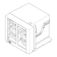
Removal and Assembly of Pump Heads, Valve Heads, and Diaphragms:

  • Under normal usage, diaphragms and valve plates rarely need replacement. If function checkup benchmarks (6.1) are not met, pump heads, diaphragms, and valve heads should be cleaned.
  • If performance doesn't improve, valve heads (38025) and diaphragms (Spare Parts Set 38120) may need replacement.
  • Attention: Disconnect the apparatus from the power source before replacing diaphragms.
  • Pump head parts are delicate; handle glass heads, valve heads, and diaphragms carefully to avoid mechanical damage (nicks, chips, deformation). Inspect parts before assembly.

Removal and Cleaning of Valve Head:

  1. Release black hose couplings GL-14 between pump heads.
  2. Loosen and remove the 4 screws on the valve head top using the provided allen wrench.
  3. Carefully remove the valve head top with the valve head and glass head.
  4. Place the entire part on a soft surface. Remove the glass head by applying light pressure.
  5. Clean valve head, glass head, and diaphragms with a suitable cleansing agent (e.g., acetone). For stubborn contamination, use an ultrasonic bath.
  6. Avoid hitting glass head sides/edges; a dropped glass head may break if reused.

Removal of Diaphragms:

  • Only remove diaphragms if broken or un-cleanable while mounted. Release by turning counterclockwise.

Replacement of Diaphragms:

  • Ensure the diaphragm holder fits tightly on the lower side of the diaphragm, with no gap between holder and diaphragm.
  • Carefully screw on and tighten the diaphragm and holder by hand with the same force used for detachment. Recheck for gaps.

Replacement of Pump Head and Assembling:

  1. Before replacing, check if valves are stuck by holding the head between two fingers and shaking; a soft clicking should be heard.
  2. Place the valve head into the valve head top, ensuring the rubber sealing is symmetrical. Snap the glass head into the top, aligning knobs with spaces on the valve head. Place the assembled pump head on the diaphragms.
  3. Attention: Arrows on the upper part of valve heads must point in the same direction on both pump heads.
  4. Use the setting gauge (side 1) between the metal top and thread. Screw in the first screw (a) until the gauge can be removed without force. Repeat for screws (b), (c), and (d) crosswise.
  5. Change to setting gauge side 2. Place it between metal top and thread. Screw in screw (a) a quarter-turn, then (b), (c), and (d) similarly. Repeat until the gauge cannot be removed without force. Loosen the screw slightly to remove the gauge and leave it in that position.
  6. Use the short red part of the allen wrench to tighten screws for correct tightness. Only use screws with a blue spot (Tufloc coating) to prevent loosening during operation/transport. New screws may require slightly more force, which is acceptable.
  7. Connect the connecting hose, tighten connections, and assemble the second pump head similarly.
  8. If vacuum is not achieved, replace or clean valve head seals. Remove valve heads (6.2. 1-4), carefully take out white sealing rings with a valve reed, and place in an ultrasonic bath.
  9. Refit cleaned/replacement parts as shown in the diagram.

Function Control:

  • Perform annually.
  • Pump: Suction time for a dry volume of 3 liters at 20 mbar should not exceed 60 seconds.
  • Inspect hoses regularly for brittle areas and leaks.
  • If the pump doesn't meet specifications, clean and replace diaphragms and valve heads as needed.

Customer Service:

  • Work on the apparatus must be performed by authorized service personnel.
  • BÜCHI customer service provides spare parts, repair, maintenance, and technical consulting.

Working with Strong Acids/Bases:

  • When removing strong acids/bases with a vacuum pump, wear protective clothing (goggles, laboratory coats).
  • Rinse the pump after use by sucking 5-10 ml of water through the pump inlet and collecting it directly after the pump outlet. Repeat until the pH of the liquid from the pump outlet is between 3-9.
  • Dry the pump by sucking air through it for 2-3 minutes.

Shutting Down:

  • Before moving, disconnect the power cable and all hoses.
  • Storage/Transport: Clean thoroughly (6.1), remove all chemicals, wash glass parts. Return to original packaging.
  • Disposal: Refer to Chapter 9 (Appendix) for materials used to ensure proper disposal according to environmental regulations. Observe regional and local statutes.

Buchi Vac V-511 Specifications

General IconGeneral
BrandBuchi
ModelVac V-511
CategoryWater Pump
LanguageEnglish

Related product manuals