12
BÜCHI Vac V-511/512/5134 Beginning Operation
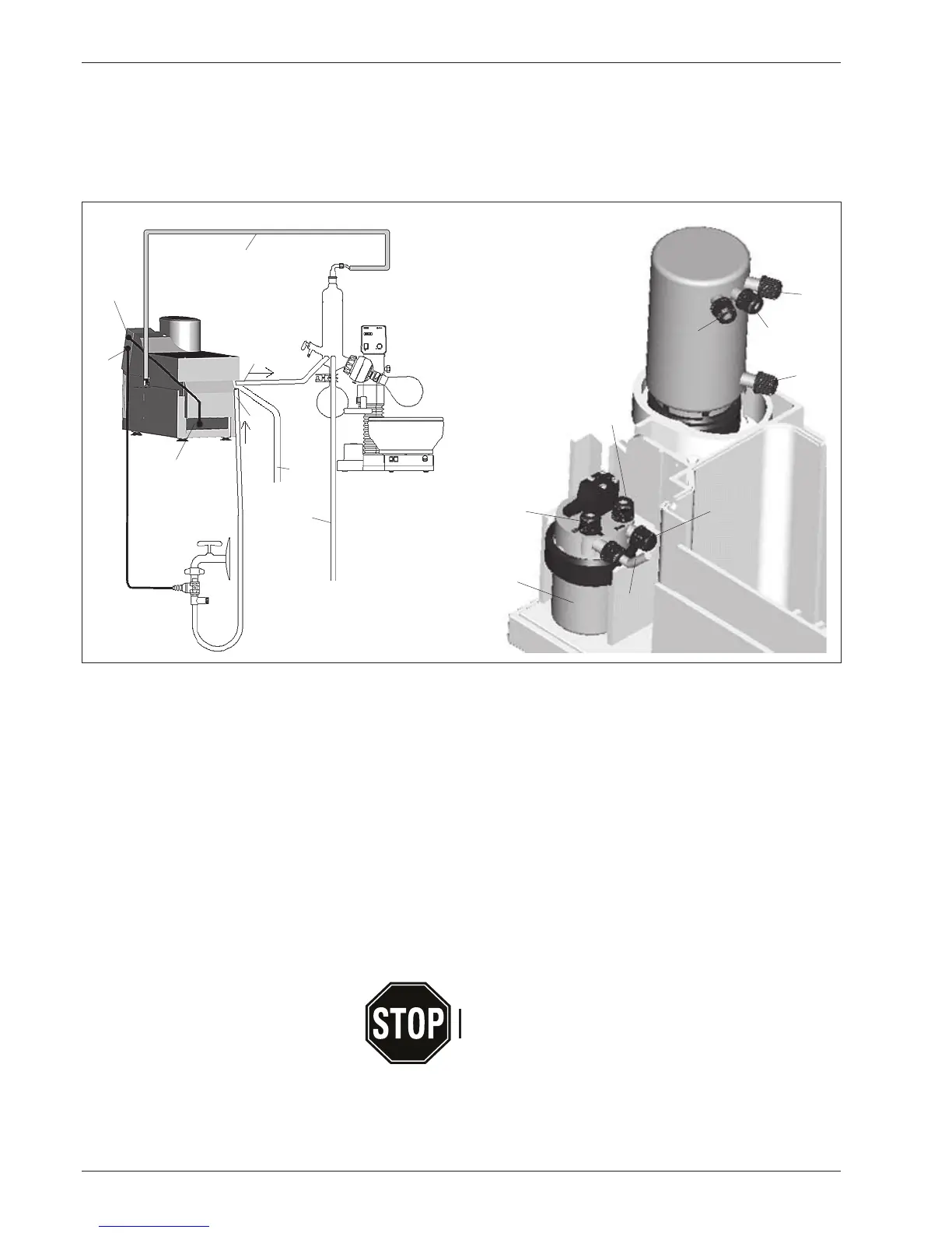
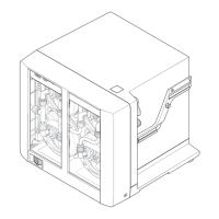
Fig. 9: Installation diagram 1
햲
햸
햴
햶
햵
햷
햳
햴
햵
햹
햺
햷
햻
햽
햾
햽
햿
Connections to a Rotavapor
햲 Control cable V-800 to pump
햳 Cooling water valve on the "CW" connection
햴 Cooling water inlet (CW in)
햵 Cooling water outlet to Rotavapor (CW out)
햶 Cooling water outlet from Rotavapor
햷 Vacuum hose to Rotavapor (red hose)
햸 Power cable socket
햹 Hose connection to V-800
햺 Hose connection to pump
햻 Connection to pump outlet
햽 Exhaust hose ∅14mm
햾 Woulff-bottle
햿 Connection to further user (cf. Page 15)
The inert gas ventilation of the Rotavapor is handled by the
Vacuum Controller (cf. Page 20).
During operation, the valve unit is in a vacuum. Please inspect
glass parts for splinters or cracks.