SECTION Q
Fine Calibration *
1. After the M-500 has been on for 1 hour run a refrnc / background run and a .05 mm polystryene film run. This can be done with the
EZ-Scan or Grams/AI software programs.
2. Find the actual values of the 2850.7 and 906.7 peaks. The difference should be 1944 cm
-1
plus or minus 2 cm
-1
.
3. If the span is off by a small amount (<10 cm
-1
) use a 5/64" Allen key with a 11/32" open end wrench to adjust the # 8-32 set screw
on the left side of optic M4. (Note 1 degree of turn is equal to about 2 cm
-1
. Turn clockwise to decrease the span and counter
clockwise to increase the span. It may be necessary to release the screw's locking compound with acetone.)
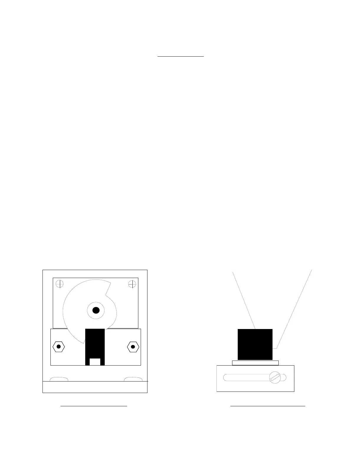
4. Look at the relative position of the scan motor blade to its fine sensor at 4000 cm
-1
, this is home position.
5. For linear adjustments less than 20 cm
-1
with the power on - a) rotate the scan motor blade counter clockwise for positive .8 cm
-1
steps (clockwise - negative), b) loosen the panel style hex nut on the blade with a 14mm wrench, c) slip the blade back to home
position and d) re - tighten the nut e) push the reset button on the M-500.
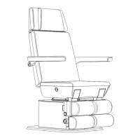
6. For greater than 20 cm
-1
linear adjustments use the coarse sensor between M3 & M4. (Move forward for positive and backward for
negative. Looking directly down on top of the coarse sensor pickup the back edge of the wavenumber cam should be exactly in the
middle of the coarse sensor.)
7. For large non-linear errors make sure the optics M3 & M4 are correctly seated in their kinematic mounts. (This could show an error
of almost 300 cm
-1
at 2850. The plates should be about 1/4" from the mount and the 3 set screws should go to the flat, slot and hole.
They are held under tension by a # 10 locknut, washers and spring.)
8. *This picture is for the older M500’s that have a double shafted motor with a half circle chopper blade on the right side of the
wavelength drive motor. The new stronger motors use an adapter with the sensor on the left side. The chopper blade looks like a
bow tie with the trailing edge of one blade half way through the sensor. The blade from the left side of the instrument turns ccw.
If your numbers are for example 10 numbers low you can scan to 3990 loosen the nut and slip the blade back to the start point.
Lock the nut and reset the instrument to 4000.
Fine Sensor 4000cm-1 Course Sensor 4000cm-1