Mounting Instructions 1
5
Electrical connections must be made according to
the wiring diagram (See pages 28-31).
All the wires should be routed through the cable
raceway at the rear of the boiler. Rear panel jacket
may be modified per local code.
Use the white strain reliefs provided to lock all cables
into place on the back of the control.
Replace the top housing of the control and fasten
the two screws. The control is ready to be placed
into operation.
Tilt the display to the desired position.
1 Mounting Instructions
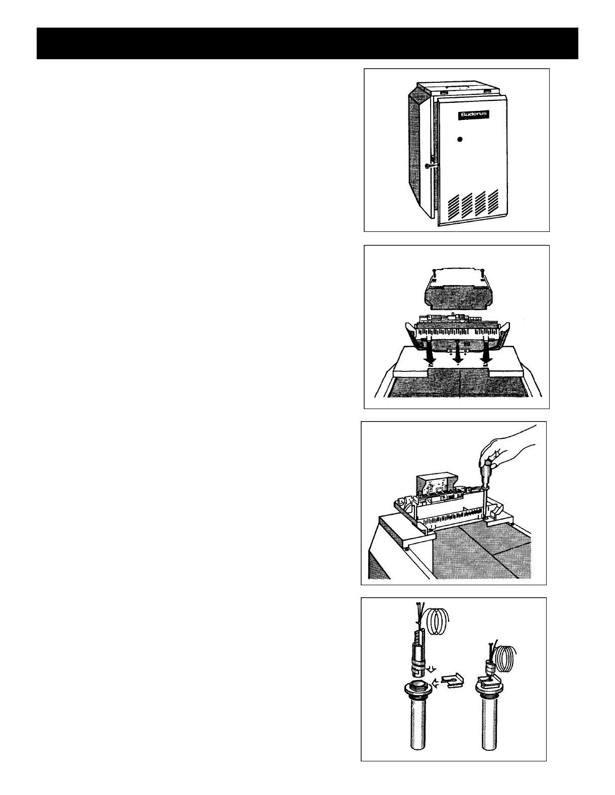
4
Remove the front panel of the boiler.
• Only necessary with G124X and G224
Remove the two screws and housing from the top of
the Ecomatic.
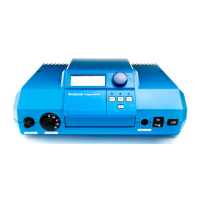
Insert the two front feet of the control
into the holes provided on the top of the
boiler. Then, firmly push down on the
rear of the control until it snaps into place.
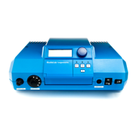
The sensor bundle consists of one thermistor (FK), two
capillaries and a spacer. Mount the sensors per the following
boiler specific instructions.
G115, G205, G305: Replace brass well with chrome
Ecomatic well. The sensor bundle should be inserted
into the Ecomatic well.
G124X: Unwrap the sensor bundle. Remove spacers from
the chrome well on the boiler. The high limit (STB) capillary
and temperature sensor (FK) should be inserted into the
chrome well with existing Honeywell Aquastat. The
remaining capillary should be mounted to the supply
manifold and thoroughly insulated.
G224: The tridicator assembly should be moved to the
supply piping and replaced with the chrome plated Ecomatic
well. The sensor bundle should be inserted into this well.
Fasten the control to the boiler jacket
using the two screws as shown.