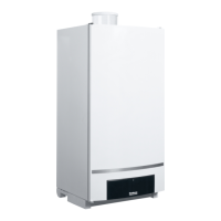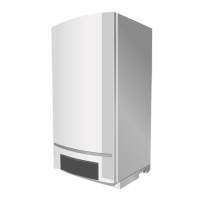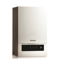
Do you have a question about the Buderus Logamax GB062-24 KDH V2 and is the answer not in the manual?
| Model | Logamax GB062-24 KDH V2 |
|---|---|
| Fuel Type | Natural Gas / LPG |
| ErP efficiency class heating | A |
| ErP efficiency class DHW | A |
| Max. working pressure | 3 bar |
| Flue gas connection | 60/100 mm |
| Type | Wall-mounted boiler |
| Output | 24 kW |
| Connection for heating flow | G 3/4 |
| Connection for heating return | G 3/4 |
| Connection for gas | G 1/2 |
| Connection for DHW | G 1/2 |
Explains warning symbols, signal words, and note indicators used in the manual.
General safety guidelines for installation, operation, maintenance, and handling combustible materials.
Guide on how to access, navigate, and operate the appliance's service menu.
Overview of the structure and access methods for service functions.
Limits output for heating between min/max rated output.
Limits DHW output between min/max rated output.
Configures pump operation when the burner is off.
Sets the maximum flow temperature for heating.
Activates venting function after maintenance.
Adjusts control unit to appliance type, output, and DHW heating.
Changes the actual gas type used by the appliance.
Lists and describes faults without specific error codes.
Troubleshooting steps for fault code CL (DHW sensor).
Troubleshooting steps for fault code 5L (BUS communication).
Troubleshooting for fault code CP (cylinder/tank sensor).
Troubleshooting for fault code 3Y (differential pressure switch).
Troubleshooting steps for fault code 3C (fan speed).
Troubleshooting for fault code 2E (low system pressure).
Troubleshooting for fault code 8Y (external switching contact).
Troubleshooting steps for fault code 4Y (flow temperature sensor).
Troubleshooting for fault code 4C (temperature limiters tripped).
Troubleshooting steps for fault code 6A (no flame detected).
Troubleshooting for fault code EC (internal fault/mains voltage).
Troubleshooting for fault code 6C (flame detected when burner off).
Troubleshooting for fault code P (appliance type not defined).
General safety guidelines for inspection and maintenance procedures.
Procedures for inspecting and testing the heat exchanger.
Steps for checking and cleaning electrodes and heat exchanger.
Procedure for cleaning the condensate trap.
Procedure for checking the strainer in the cold water pipe.
Steps for checking the diaphragm in the mixer unit.
