EasyManua.ls Logo

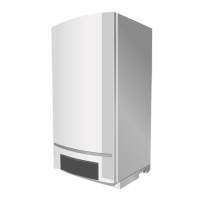
Buderus Logamax plus GB162-80 kW User Manual

Buderus Logamax plus GB162-80 kW
16 pages
To Next Page IconTo Next Page
Page #1 background imageLoading...
Page #1 background image
Gas valve replacement
Condensing gas boiler
Logamax plus
GB162-80 kW/100 kW
6 720 615 152 (01/2008) US/CA
For the contractor
Please read these
instructions carefully!
Required Input Rates
This instruction is for replacing the gas valve for the GB162 model
boilers with Natural Gas.
Notice! Save these instructions for later use.
Logamax plus GB162-80 kW
290,000 btu/hr
Logamax plus GB162-100 kW
333,000 btu/hr
WARNING!
Replacement of a gas valve must be done by a qualified service
agency in accordance with the manufacturer's instructions and
all applicable codes and requirements of the authority having
jurisdiction.
The information in these instructions must be followed to
minimize the risk of fire or explosion or to prevent property dam-
age, personal injury or death. The qualified service agency is
responsible for the proper installation of this gas valve.
The installation is not proper and complete until the operation of
the converted boiler is checked as specified in the manufac-
turer’s instructions supplied with the gas valve.
CAUTION!
The gas supply shall be shut off prior to disconnecting the elec-
trical power, before proceeding with the conversion.
Instructions

Other manuals for Buderus Logamax plus GB162-80 kW

Question and Answer IconNeed help?

Do you have a question about the Buderus Logamax plus GB162-80 kW and is the answer not in the manual?

Buderus Logamax plus GB162-80 kW Specifications

General IconGeneral
TypeCondensing boiler
Output80 kW
NOx EmissionClass 5
MountingWall-mounted
Operating Pressure3 bar
Max. Flow Temperature85 °C
Fuel TypeNatural Gas, LPG
Heat Exchanger MaterialAluminium-Silicon

Summary

Safety considerations

Application purpose

Document purpose: replacing gas valve for Logamax plus GB162-80/100 kW.

Hazard definitions

Defines risk terms (DANGER, WARNING, CAUTION, NOTICE) for hazard communication.

Observe the following symbols

Explains DANGER and CAUTION symbols for gas explosion and electrical shock hazards.

Gas valve replacement

Testing for gas leaks

Procedures for checking the external tightness of the gas supply valve and ensuring no leaks.

Inlet gas pressure

Steps to measure the gas supply pressure, including gauge connection and valve operation.

Checking and adjusting the gas/air ratio

How to check and adjust the gas/air ratio using the burner pressure nipple and adjustment screw.

Carrying out a tightness test

Instructions for checking gas circuit gaskets and joints for leaks during operation using foaming agent.

Measuring the carbon monoxide content (CO)

Procedure for measuring CO levels on the flue gas sampling point and identifying potential issues.

Lighting Instructions

Safety precautions and procedures for lighting the boiler, including actions for gas detection.
Related product manuals