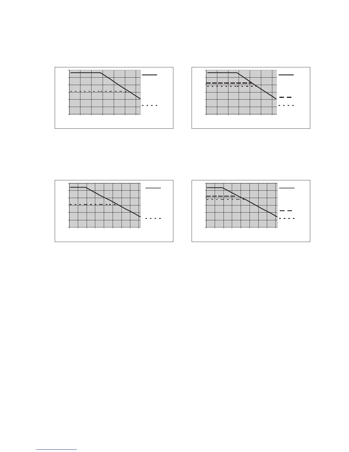
Limit for
2xMTG
Limit for
2xMTG
One heat exchanger
Model PKE 511
Nominal cooling capacity (at 77 °F) 95 Btu/hr
Max. ambient temperature 104 °F
Drift over full range ± 2.7 °F
Dew point noise static ± 0.18 °F
Two heat exchangers
Model PKE 512
Nominal cooling capacity (at 77 °F) 95 Btu/hr
Max. ambient temperature 104 °F
Dew point noise static ± 0.18 °F
Drift over full range ± 2.7 °F
Temperature differential between
heat exchangers < 0.9 °F
Model PKE 521
Nominal cooling capacity (at 77 °F) 85 Btu/hr
Max. ambient temperature 122 °F
Dew point noise static ± 0.18 °F
Drift over full range ± 2.7 °F
Model PKE 522
Nominal cooling capacity (at 77 °F) 85 Btu/hr
Max. Ambient temperature 122 °F
Dew point noise static ± 0.18 °F
Drift over full range ± 2.7 °F
Temperature differential between
heat exchangers < 0.9 °F
Note
: The limits in the diagrams for the PTG, PTV respectively MTV are for a dew point of 104 °F.
Heat Exchanger
The energy content of the sample gas and, as a result, the required cooling capacity of the gas cooler is determined by 3
parameters: gas temperature , dewpoint (moisture content) and flow v. The outlet dew point rises with increasing energy
content (heat) of the gas. The required cooling capacity is determined by the maximum acceptable level of the outlet dew point.
The following table shows cooler performance assuming the following conditions: =120 °F and =160 °F. Indicated is the v in
lpm cooled air (i.e. after the moisture has condensed). With other dew points and gas inlet temperatures the values may differ.
Jt
tJ
Ge
e G max
Please contact one of Buhler’s application specialists for assistance and further information.
Heat exchanger GPTS PTG PTV MTS MT MTV
PTS-I PTG PTV-I MTS-I MTG MTV-I
3) 3) 3)
2) 2) 2) 3) 3) 2) 3)
)
)
)
)
Flow rate v 7.5 lpm 4.2 lpm 4.2 lpm 5 lpm 3.5 lpm 3.2 lpm
Inlet dew point 150 °F 150 °F 150 °F 150 °F 150 °F 150 °F
Gas inlet temp. 356 °F 284 °F 284 °F 284 °F 284 °F 284 °F
Max. cooling capacity Q 142 Btu/hr 85 Btu/hr 85 Btu/hr 90 Btu/hr 76 Btu/hr 62 Btu/hr
Gas pressure p 2320 psi 43 psi 29 psi 363 psi 43 psi 29 psi
Pressure drop p (v=2.5 lpm) 0.15 psi 0.15 psi 0.15 psi 0.29 psi 0.28 psi 0.26 psi
Dead volume 1.8 cu. in. 1.8 cu. in. 3.5 cu. in. 1.2 cu. in. 1.1 cu. In. 1.0 cu. in.
Swagelok GL 14 (0.2 in.) DN 4/6 tube 0.2 in. GL14 (0.2 in.) DN 4/6
1/4” GL 14 (1/4”) 1/4”-1/8” tube 1/4” GL14 (1/4”) 1/4”-1/8”
G 3/8“ GL 25 (0.5 in.) G 3/8" G1/4” GL18 (0.3 in.) G 1/4”
NPT 3/8“ GL 25 (1/2”) NPT 3/8" NPT 1/4” Gl18 (0.3 in.) NPT 1/4”
max
e,max
G,max
max
max
1)
1)
1)
4
4
4
4
1)
2)
3)
4)
t
J
D
Sample gas connections (metric) 0.2 in.
(US)
Condensate outlet connection (metric)
(US)
Consider the maximum cooling capacity of cooler
Types marked “I” have NPT-threads or US tubes, respectively
Heat exchangers MTS, MTG and MTV cannot be automatically drained
Inner diameter gasket
DA 440012
Page 3/4
10/2013


 To Next Page