This document provides operating instructions for the Bühler AG Three-roll Mill, models SDW 800/1000 and SDW 800/1000-Ex. The manual covers basic information on design, installation, start-up, operation, and maintenance. A separate Spare Parts Catalogue (80394) is also an integral part of the operating instructions.
General Description and Function
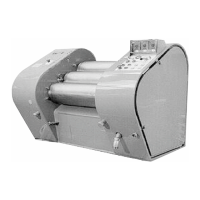
The Three-roll Mill is designed for dispersion, homogenization, and disagglomeration of suspensions ranging from liquid to highly viscous. Typical applications include offset printing inks, paints, pigment dispersions, colored pencil cores, artists' colors, coating substances (PVC pastes), and chocolate and confectionery masses.
The machine features three counter-rotating rolls (Roll 1, Roll 2, Roll 3). Rolls 1 and 2 are flexible and are hydraulically pressed against the fixed Roll 3. The extent of the nip (the gap between rolls) depends on the hydraulic roll contact pressure, roll speed, and product properties (e.g., viscosity).
Product is fed between Roll 1 and Roll 2. Initial dosing and slight dispersion occur in the first nip. The main dispersion happens in the second nip between Roll 2 and Roll 3, where the average speed is 3-4 times higher than in the first nip. A scraper knife then removes the product from Roll 3, which drains across an apron.
The mill has different operating positions:
- Mixing: Rolls 1 and 2 are pressed against each other, while Rolls 2 and 3 are released. The scraper knife and apron are slightly detached from Roll 3. Product runs through the first nip and returns to the product trough, used for starting the machine and tempering rolls/product.
- Grinding: All three rolls are pressed against each other. The apron and scraper knife are pressed against Roll 3. Product is dispersed through both nips and scraped off Roll 3.
- Loosen: All three rolls are released from each other, and the scraper knife and apron are slightly detached from Roll 3. This is the neutral position or used for cleaning.
The rolls are cambered chilled-iron rolls, designed to maintain a consistent nip length despite deflection under pressure. These rolls are suitable for operation within a narrow pressure range.
Hydraulic System
The rolls, hopper plate, and apron are hydraulically pressed. An electrically driven hydraulic pump generates the pressure, pumping oil from the tank to the hydraulic cylinders.
Key hydraulic components include:
- P1 Hydraulic pump: Runs in oil.
- F1 Suction filter: Cartridge needs cleaning during oil changes.
- M251 Hydraulic pump motor: Drives the hydraulic pump via an elastic coupling.
- HV19 Maximum operating pressure valve: Sets pressure approximately 10 bar above optimum roll pressure (70 bar with tilting device).
- HV15 Non-return valve: Prevents immediate pressure drop during power failure.
- HV1 Roll position lever: Selects operating modes ("Loosen," "Mixing," "Grinding").
- HV2/HV3 Pressure reducing valves: Set roll-contact pressure on drive and cooling sides.
- HV7 Pressure reducing valve: Sets hopper plate contact pressure (approx. 15 bar).
- HV8 Pressure reducing valve: Sets scraper knife contact pressure (approx. 10 bar).
- HV16/S267 Overpressure safety control device: Interrupts the motor protection circuit breaker if foreign objects cause a rapid pressure increase.
- HV22 Pressure reducing valve: Sets counter-pressure for nip formation in "Loosen" and "Mixing" positions.
- S271/S272 Pressure switches: Release the main motor in "Loosen" mode (with safety bar).
- Y281 Solenoid valve: Fixes the safety bar in "Loosen" mode.
Optional hydraulic components include:
- HV6 Differential pressure valves: For the filling hydraulic system, increasing product throughput by reducing pressure in the lower passage.
- Bucket tilting device (option): Operated by a separate hydraulic system to avoid pressure variations in the roll contact pressure system.
Technical Specifications
Weight:
- Machine (SDW-800): 2500 kg
- Machine (SDW-1000): 2600 kg
- Control cabinet: 150 kg
- Roll (SDW-800): 250 kg
- Roll (SDW-1000): 320 kg
Dimensions:
- SDW-800: Length 1910 mm, Width 1210 mm, Height 1355 mm, Roll diameter 300 mm, Roll working length 800 mm.
- SDW-1000: Length 2110 mm, Width 1210 mm, Height 1355 mm, Roll diameter 300 mm, Roll working length 1000 mm.
- Control cabinet dimensions vary based on additional fittings.
Power Rating:
- Voltage: 3 x phase voltage
- Frequency: 50/60 Hz
- Control voltage: 115/230 VAC, 24 VDC
- Main motor (SDW-800): 30 kW
- Main motor (SDW-1000): max. 37 kW
- Hydraulic pump motor: 0.75 kW (without bucket tilting device), 1.10 kW (with bucket tilting device).
Roll Cooling:
- Water inflow pipe: min. DN20, min. 2 bar pressure.
- Cooling water inflow: R 3/4" (inner thread).
- Cooling water outflow: R 2" (outer thread).
- Cooling water throughput: max. 2.5 m³/h.
- Temperature regulation: Individual for each roll. Uses PT100 resistance thermometer (non-Ex) or thermostat sensor (Ex).
- Cooling water must run out free of pressure.
Hydraulic System (Specifications):
- Pump rating: 0.75 kW (1.10 kW with bucket tilting device).
- Maximum pressure: 100 bar.
- System pressure: max. 70 bar.
- Oil flow quantity: 2.8 l/min at 1450 min⁻¹.
- Tank volume: about 25 l.
- Hydraulic oil cooling: Connected to cooling water inflow. Max. temperature approx. 50-60°C.
Noise Data:
- Equivalent, workplace-related sound pressure level (Leq): 72 dB (A).
- Acoustic power level (Lw): 88 dB (A).
- Measuring surface measure (Ls): 16 dB (A).
Usage Features
- Safety: The machine is equipped with protection and safety devices. Operation requires adherence to all instructions, especially regarding nip hazards (no reaching in, appropriate gloves/sleeves), emergency stops, and proper lockout procedures during maintenance.
- ATEX Certification: Models certified for explosion-dangerous areas (SDW 800/1000-Ex) require strict adherence to ATEX 95 directive, including approved products (up to temperature class T3), specific cleaning agents, and placement of the control cabinet outside the hazardous area.
- Product Trough: Located between Rolls 1 and 2, with optional level monitoring (ultrasonic sensor) to prevent dry running or control product feeding.
- Hopper Plates: Hydraulically pressed laterally onto roll collars, available in grey cast iron (standard), bronze, or plastic (options).
- Scraper: Scrapes product from Roll 3. Contact pressure is adjustable via HV8. Scraper knife alignment is adjustable via spindles. Various scraper knife designs are available (standard, spring steel disposable, ceramic blade).
- Safety Bar: Covers the first nip during cleaning and prevents foreign objects from falling in. The machine can only start in "Loosen" mode with the safety bar inserted.
- Roll Nip Setting (Option): Handwheel-adjustable mechanical setting for processing low-viscosity products.
- Protective Cover (Option): Secures rolls and feeding nip during production. Machine can only start in "Mixing" or "Grinding" mode with the cover installed. Must be earthed and closed carefully to avoid sparks.
Maintenance Features
- Pre-operational Inspections: Before start-up, all transport aids must be removed, electrical installations checked, hydraulic and gear oil levels correct, motors and bearings lubricated, and safety devices operational.
- Maintenance and Lubrication Chart: Provides a schedule for daily, weekly, monthly, every three months (or 500 hours), annually (or every 1000 hours), and every four years (or 8 hours of operation) / after 10000 hours of operation (or during revision) checks and activities.
- Cleaning: Cleaning intervals depend on product, location, and climate. Only authorized personnel should perform cleaning. Specific cleaning agents (up to temperature class T3 for Ex models) and procedures for rolls are outlined, including the use of cleaning paste.
- Hopper Plate Maintenance: Sealing tracks are prone to wear. Hopper plates can only be removed in "Loosen" mode with the hydraulic pump running.
- Water Filter Cleaning: Cartridge should be removed, rinsed, and replaced if necessary.
- Spare and Wear Parts: Bühler AG recommends keeping important spare and wear parts in stock (hopper plates, scraper knife, rolls, V-belts). Only original spare parts should be used for Ex models to maintain ignition protection.
- Disposal: Metal parts should be scrapped by type, plastic parts recycled, liquids drained into special containers for treatment, and special waste disposed of according to regulations.
- After-sales Service: Bühler AG offers customer support for problems, questions, briefing, start-up, installation, and maintenance.