5
PLUMBING REQUIREMENTS
The dispenser must be connected to a COLD WATER system with
an operating pressure between 30 and 100 psig (.207 and .690 mPa).
This water source must be capable of producing a minimum flow rate
of 3 fluid ounces (88.7 milliliters) per second. A shut off valve should
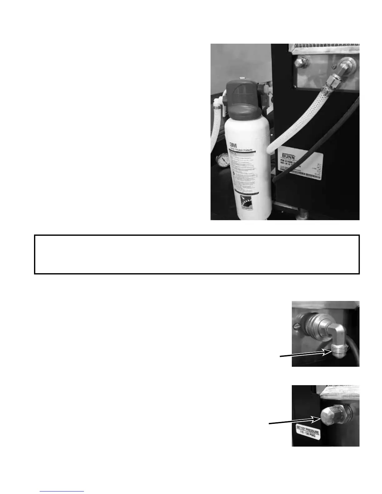
be installed in the line that will supply the dispenser. A water filter has
been included with the dispenser. The water filter should be installed
as close as possible to the inlet of the machine, but downstream
of the shut off valve (see Figure 2). The new water filter should be
flushed with at least five gallons of water before hooking it up to the
dispenser. The main water inlet is a 3/8” (9.52 mm) MFL connection.
NOTE- At least 18 inches (457 mm) of an FDA approved flexible bev-
erage tubing, such as reinforced braided polyethylene, before the
dispenser will facilitate movement to clean the countertop. It can be
purchased direct from BUNN-O-MATIC (part number 45848.10__
[see Illustrated Parts Catalog for complete part number.])
BUNN-O-MATIC does not recommend the use of saddle valves to
install the dispenser. The size and shape of the hole(s) made in the
supply line(s) by saddle valves may restrict water flow.
As directed in the International Plumbing Code of the International Code Council and the Food Code Manual of
the Food and Drug Administration (FDA), this equipment must be installed with adequate backflow prevention
to comply with federal, state and local codes. For models installed outside the U.S.A., you must comply with
the applicable Plumbing /Sanitation Code for your area.
PLUMBING HOOK-UP
The plumbing connection is a 3/8” male flare adapter located on the rear of the water dispenser
(Figure 3).
NOTE – Water pipe connections and fixtures directly connected to a potable water supply shall
be sized, installed, and maintained in accordance with federal, state, and local codes.
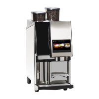
CARBON DIOXIDE HOOK-UP
The dispenser will need to be connected to an external CO
2
source. An external CO
2
pressure regulator will need to be installed in the supply line to the dispenser. The
external CO
2
supply connection is a ¼” MFL (Figure 4) located on the back of the
machine.
Figure 2
P4372
Figure 3
Figure 4
52373.0 103015